
Mosquito repelant circuit

The output signal will thus be a non-symmetrical waveform. Such a non-symmetrical signal contains more high frequency harmonics compared to the normal square wave signal. The output of the circuit will have the basic frequency of 5 KHz along with harmonics of 10, 15, and 20 KHz. If some insects are deaf to frequencies up to 5 KHz, they may react to 10 KHz or 15 KHz or even 20 KHz, one never knows...
The piezo buzzer used should not have an internal oscillator built into it. The circuit consumes 0.3 mA current and can give about 1500 hours of nonstop operation.
The astable multivibrator circuit is constructed using two NPN transistors (T1 and T2), which are alternately turned on and off. The configuration allows for continuous oscillation, generating a square wave output. The frequency of oscillation is determined by the values of the capacitors (C1 and C2) and resistors connected to the base of each transistor. The charging and discharging time of the capacitors creates the time delay necessary for the transistors to switch states, resulting in a square wave output.
In this particular application, the capacitors C1 and C2 are chosen such that C2 is four times the capacitance of C1. This imbalance leads to a non-symmetrical output waveform, which is crucial for generating higher frequency harmonics. The output frequency can be calculated using the formula:
\[ f = \frac{1.44}{(R1 + R2) \cdot (C1 + C2)} \]
where \( R1 \) and \( R2 \) are the resistances connected to the base of the transistors, and \( C1 \) and \( C2 \) are the capacitors. The resulting waveform will have a fundamental frequency of around 5 KHz, with additional harmonics at 10 KHz, 15 KHz, and 20 KHz, which may be effective for repelling certain types of insects.
The output of the circuit drives a piezo buzzer, which converts the electrical signal into audible sound. It is critical to ensure that the piezo buzzer does not incorporate an internal oscillator, as this could interfere with the intended operation of the multivibrator circuit. The low current consumption of 0.3 mA allows for prolonged operation, estimated at approximately 1500 hours, making this circuit a practical solution for insect repellent applications.The Astable Multivibrator, which is generally used as a signal generator, is once again used here to generate the desired frequencies. It is an excellent example of the fact, how versatile simple basic electronic circuit can be. It seems quite obvious then, that by creating these insects frequencies electronically, we should be able to repel these insects!
The most important point to remember here is that, unfortunately, this method has so far not been completely sucessfull. Whereas one group of insects can be made to run away at frequencies around 5 KHz, other types may desert only at higher frequencies, about 10 to 20 KHz.
For some types, all the frequencies may fall on deaf ears! Yet other theories propose that in fact some frequencies may even attract them instead of repelling. Let us quicklt see the operation of the astable multivibrator circuit. When T1 is conducting T2 is off and when T2 is conducting, T1 is off. The capacitors C1 and C2 contributes decisively to this ON/OFF cycles for the transistors T1 and T2. The time taken by C1 and C2 to charge and discharge decides the shape of the output waveform. Another important factor in the operation of the circuit is the fact that the transistor goes into conduction only when the base-emitter voltage exceeds 0.7 volts (for silicon transistors). From this basic knowledge we can visualise how the transistors exchange their roles and how the voltage on the collector of each transistor jumbs between the lower and upper level, producing a rectangular waveform.
If you take a close look at circuit, you will notice that C1 and C2 are not equal. They differ in their values by afactor of four. The output signal will thus be a non symmetrical waveform. Such a non symmetrical signal contains more high frequency harminics compered to the normal square wave signal. The output of our circuit will have the basic frequency of 5 KHz along with harminics of 10, 15 and 20 KHz.
If some insects are deaf to frequencies upto 5 KHz, they may react to 10 KHz or 15 KHz or even 20 KHz, one never knows ... The piezo buzzer used should not have an internal oscillator built into it. The circuit consumes 0.3 ma current, and can give about 1500 hours of nonstop operation. 🔗 External reference
Related Circuits

The divider acts as the speaker's brain and is crucial for sound quality. The music amplifier's output signal must be processed through a wave filter element to divide it into specific frequency signals for each unit. A scientifically and...

This field strength meter consists of a tuned crystal detector that generates a DC output voltage from a transmitted signal. The DC voltage is utilized to modulate the frequency of a transmitter with a power output of 100 mW,...

Pressing the START pushbutton activates either the headlights or spotlights for a specified duration. After 1 minute, determined by R1 and C1, the lights will turn off as the NE555 timer completes its cycle. The circuit utilizes a NE555 timer...
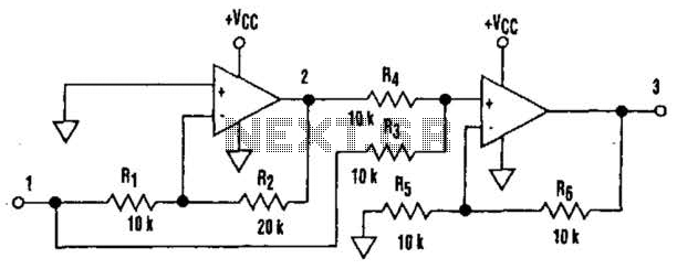
It is well understood that utilizing single-supply operational amplifiers (op amps) can present challenges when implementing simple functions in a bipolar signal environment. Often, this necessitates the use of additional op amps and other electronic components. Considering this, it...
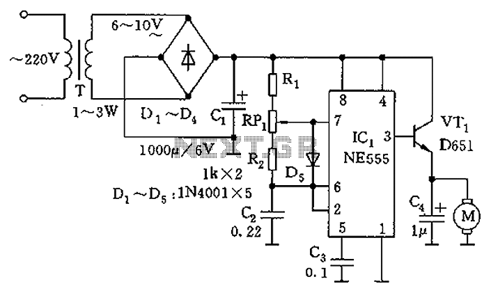
The circuit utilizes a 555 timer as the core component to create an astable multivibrator. The oscillation period T is given by the formula T = 0.693 (R1 + 2R2) C1, which corresponds to an oscillation frequency of approximately...
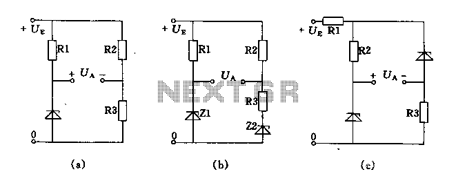
The circuit depicted in Figures A, B, and C demonstrates a high voltage coefficient. When the regulator resistance \( r_z \) is held constant, the bridge configuration achieves an infinite voltage coefficient. In Figure A, the load circuit is...