
Motion sensing LED Quantum Bits

The described circuit utilizes a light-emitting diode (LED) as an output indicator, which is powered under normal conditions through a pair of resistors, R1 and R3. The LED's brightness is maintained at a low level during idle operation, allowing for energy efficiency. The inclusion of SW1, a spring and wire-based accelerometer, serves as an activation switch that responds to motion or acceleration.
Upon activation of SW1, capacitor C2 begins to charge rapidly, influenced by the resistance value of R2. This rapid charging results in a momentary increase in voltage across the LED, causing it to illuminate brightly. The discharge path for C2 is routed through R3, which also limits the current flowing through the LED. The design allows for customization of the LED's brightness and duration of illumination by adjusting the values of R1, R2, and C2.
R1 determines the steady-state brightness of the LED when SW1 is not engaged, while R3 can be modified to set the maximum current that the LED can handle during the brief discharge period. The time for which the LED remains illuminated can be varied by changing the capacitance of C2 and the resistance of R2; larger values will result in a longer illumination duration.
Capacitor C1 plays a crucial role in stabilizing the voltage across the circuit, particularly given the high internal resistance of the battery. It is imperative to select a sufficiently large value for C1 to ensure that the voltage does not drop significantly when SW1 is activated for short intervals. This design consideration is essential for maintaining the reliability and performance of the circuit, particularly in applications where quick activation and response times are required.
Overall, this circuit exemplifies an efficient use of passive components to create a responsive LED indicator system that can be tailored to specific operational parameters through careful selection of resistors and capacitors.The circuit works like this: Normally the LED is powered dimly through R1 and R3. SW1 is the spring and wire based accelerometer I mentioned earlier. When SW1 is closed, C2 quickly charges up (at a rate defined by R2) and is discharged through R3 and the LED. The battery normally has a high internal resistance, and C1 is used to counteract that wh en SW1 is closed. Change R3 to set the max current through the LED. Change R1 to set the normal "steady" brightness of the LED. Change C2 and R2 to vary the length of time the LED is bright. And make C1 large enough that it`s voltage doesn`t change too much when SW1 is closed briefly. 🔗 External reference
Related Circuits
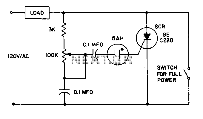
The 5AH will trigger when the voltage across the two 0 µF capacitors reaches the breakdown voltage of the lamp. Control can be obtained from full off to 95% of the half-wave RMS output voltage. Full power can be...

This circuit is a simple remote-controlled relay capable of switching lamps or other devices. D1 can be a phototransistor, LDR, or an infrared transistor. The circuit is controlled using an IR remote, similar to a TV remote control, when...
The circuit diagram presented is for an IC controlled emergency light with a charger, functioning as a 12V to 220V AC inverter circuit. Key features include automatic activation of the light during a mains failure and a battery charger...
An exhaust fan is a crucial component in kitchens. This document presents a simple circuit designed to control kitchen fans by monitoring the ambient temperature. It is built around... The circuit for controlling an exhaust fan based on ambient temperature...
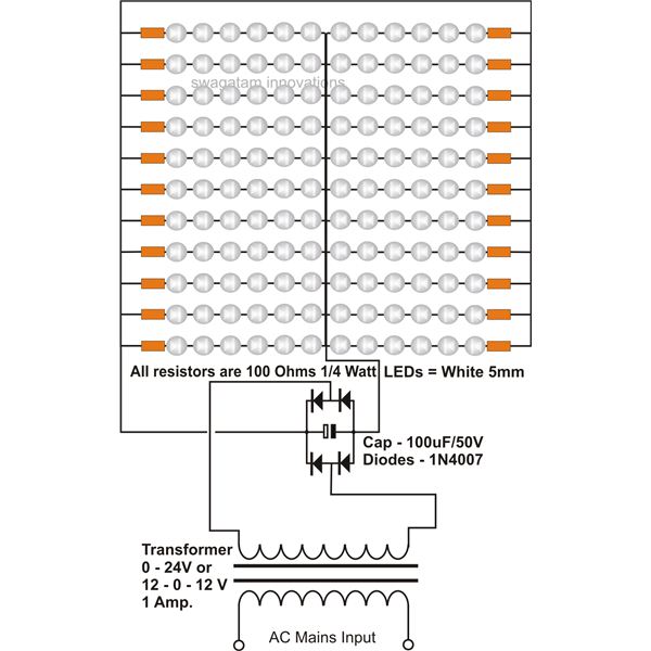
The use of white LEDs for home illumination is gaining popularity due to their high power efficiency. The diagram illustrates a simple circuit configuration that consists of multiple LEDs arranged in both series and parallel. In the LED tube...
This circuit will flash a bright LED 5000mcd as an intention getting device or fake car alarm. More: Component values are not critical and different transistors may be used. This circuit functions as a visual alert system by utilizing a...