
Motion Sensor Switch for Light

The described circuit integrates a Passive Infrared (PIR) sensor module, which is critical for detecting motion within a specified radius. The sensor is mounted at a height of 3 meters, optimizing its field of view to cover an area of approximately 10 meters in radius. The connection of the PIR module to the main circuit is facilitated through a 4-core screened cable, which minimizes interference and ensures stable communication between components.
Powering the circuit is achieved through a regulated 12V DC power supply, which can either be sourced from a conventional adapter or a solar power box, providing flexibility in installation locations. The PIR sensor's relay output is designed to toggle upon detecting movement, which triggers the MOSFET (T1) to activate. Resistor R1 serves as a current-limiting component, ensuring that T1 operates within safe parameters.
Upon activation of T1, the electromagnetic relay (RLY1) is energized, allowing current to flow to the electric sprinkler system. This relay serves as a control mechanism, enabling the sprinkler to operate only when movement is detected, thus conserving water and energy. The circuit design also incorporates spare contacts on RLY1, which can be utilized for additional functionalities, such as activating a high-power warning alarm, enhancing the system's overall utility.
T1 is configured as a mini electronic timer, which provides a delay feature. This means that even after the PIR sensor no longer detects motion and its relay output turns off, the output relay (RLY1) remains activated for a short duration. This delay is adjustable and is determined by the timing capacitor (C2), allowing customization of the system's response time to suit specific operational requirements. This feature can be particularly beneficial in applications where a sustained operation is necessary after initial activation, such as allowing the sprinkler to complete its cycle before shutting off.Install the PIR module hanging from a 3 metre high mast (to cover 10 metre radius area) and connect its supply and relay terminals to our finished and enclosed circuit, observing right polarity. A 4-core screened cable can be used for this interconnection. Power the circuit from a regulated 12VDC adaptor/solar power box. Whenever the PIR module detect movement of a live body its relay output toggles and the switching mosfet (T1) in the circuit is switched to on via resistor R1 and related parts. As as result, the EM relay at the output of T1 is activated and the electric sprinkler gets its supply through the relay (RLY1) contacts.
This contacts (or spare contacts) can also be used to activate a high-power warning alarm. Please note that, here T1 is wired as a mini electronic timer. Even after the PIR relay switched off, output relay (RLY1) remains in on state for a short duration decided by the value of timing capacitor C2. 🔗 External reference
Related Circuits
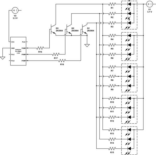
It is noted that the LEDs are not configured in parallel with the transistor. If they were, the LEDs would illuminate when the transistor is off. Instead, the LEDs are connected in parallel before entering the transistor. The transistor...

The circuit is designed to ensure that the headlights or side lights are automatically switched off after the ignition contact is turned off. This prevents the occurrence of a dead battery due to headlights being inadvertently left on. The circuit...

The circuit consists of two stages. The first stage is a switch or cut-off device. It detects a voltage above 0.7V from the solar panel, and the resistance between its collector-emitter terminals reduces to a very small value. The...

A light-emitting diode (LED) lamp is a solid-state lighting device that utilizes light-emitting diodes as its light source. LEDs are a cost-effective and convenient choice for various lighting applications. They are available in an extensive range of colors, styles,...
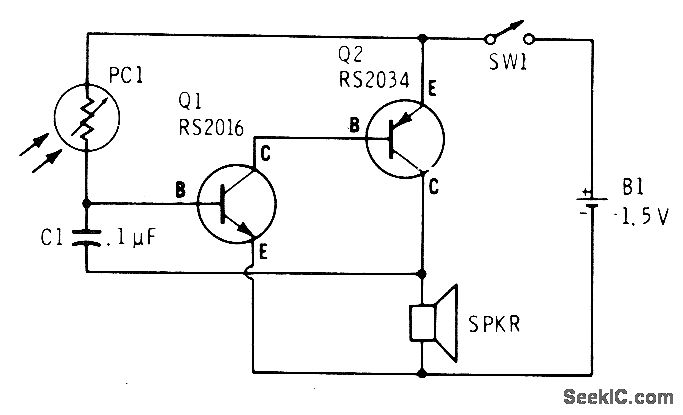
A low light condition on a cadmium sulfide photocell (Radio Shack 276-116) generates a series of clicks in a miniature 8-ohm loudspeaker. As the light intensity increases, these clicks coalesce into an audio tone that escalates in frequency with...

This circuit is a simple musical alarm that generates a tone when water or another conductive liquid touches the two sensor wires provided. It utilizes four transistors and a melody generator integrated circuit (IC) M3482. When water bridges the...