
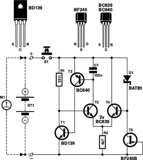
Car Headlight Alarm circuit diagram

The circuit utilizes a relay or a transistor switch to control the power supply to the headlights based on the ignition status. When the ignition is turned on, the circuit allows current to flow to the headlights, enabling them to operate normally. Once the ignition is turned off, the relay or transistor is triggered to interrupt the power supply to the headlights, effectively turning them off.
The schematic typically includes an ignition switch, a relay or transistor, and the headlight circuit. The ignition switch is connected to the control terminal of the relay or the base of the transistor. When the ignition is active, the relay is energized, closing the circuit and allowing current to flow to the headlights. Upon turning off the ignition, the relay de-energizes or the transistor turns off, cutting off the power to the headlights.
To ensure reliability, additional components such as diodes may be included to prevent back EMF from damaging the control circuitry. A capacitor can also be integrated to provide a delay if desired, allowing for a brief period during which the headlights remain on after ignition off, enhancing visibility when exiting the vehicle.
This circuit is essential in automotive applications to enhance user convenience and prevent battery drain, thereby improving the overall efficiency and reliability of the vehicle’s electrical system.First, to indicate that the head lights (or the side lights) should be switched off after switching off the ignition contact. With this circuit, there should be no dead battery due to headlights that were left on. 🔗 External reference
Related Circuits

This board layout was created using the SOIC version of a PIC16F627A without drawing the usual schematic first. Most of the part values are etched on the Layout. The SIP resistor packs I used are 10k ohm, some experimentation...
Is the battery depleted, or is there an issue with the device? This question often arises when a battery-operated device, such as a Walkman, fails to power on. Before seeking professional repair services, it is advisable to first test...
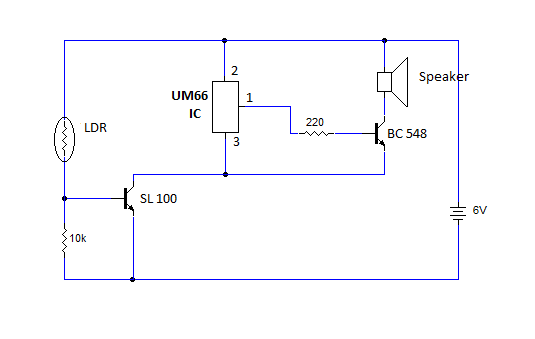
This article provides instructions for creating a light-sensitive morning alarm circuit. The circuit utilizes an LDR (Light Dependent Resistor) or photoresistor to detect morning light, which triggers the alarm section. When light is detected, the circuit produces a melodious...
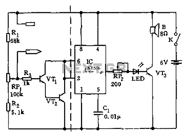
The apparatus consists of a cavers point detection circuit and a triggering display circuit. The cavers instrument functions as a test probe, which, when held in one hand, can detect acupuncture points by touching the skin with another probe....

In this multivibrator circuit, frequency and pulse width can be separately controlled by using steering diodes (1N914) and two potentiometers. This multivibrator circuit utilizes steering diodes, specifically the 1N914 type, to enable independent control over both the frequency and pulse...

A speaker system can be safeguarded against amplifier failure by detecting DC voltages on the speaker line (a-b). The circuit is capable of sensing both positive and negative DC voltages. In such instances, a relay activates to disconnect the...