
Motor Control circuit II

This circuit is designed for the control of 12-volt motors and lighting systems using Pulse Width Modulation (PWM) for efficient regulation. The core component of the circuit is the NE555 timer IC (IC1), which operates in astable mode to generate a square wave signal with a variable duty cycle. This modulation allows for precise control over the effective voltage supplied to the motor, enhancing its performance and efficiency.
The PWM signal from the NE555 is fed into a BUZ11 MOSFET (Q1), which acts as a switch to control the motor's power. The MOSFET is preferred for its efficiency, as it minimizes energy loss compared to traditional resistive methods. The circuit is designed to handle motor currents up to 10A, with thermal management provided by a heatsink rated at least 6.5 K/W, which is crucial for maintaining the performance of the BUZ11 under load.
For applications where the motor current exceeds 2A, a diode (D3, MBR1645) is used in conjunction with a heatsink to ensure safe operation. The circuit is powered by a 12V supply, but it can be adapted for higher voltages, such as 24V, by isolating the NE555 power supply from the motor voltage. This flexibility allows the circuit to accommodate various motor types and specifications.
Capacitors (C1 to C7) are used throughout the circuit for filtering and stability. The circuit also includes a snubber capacitor (47nF) that can be placed across the motor terminals to suppress voltage spikes caused by inductive loads. The inclusion of diodes (D1, D2, D4, D5) provides additional protection against reverse voltage and ensures reliability.
Resistors (R1, R2, R3) and a variable resistor (P1) are used to set the timing and duty cycle of the PWM signal. The values of these components can be adjusted to fine-tune the performance of the motor control system.
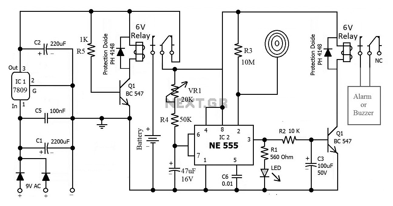
Overall, this circuit represents an efficient solution for controlling DC motors, providing enhanced torque at lower speeds and minimizing energy consumption through the use of PWM. The design is suitable for various applications, including robotics and automation, where precise motor control is essential. A printed circuit board (PCB) layout is also available, facilitating easy assembly and integration into projects.This circuit is 12 volt motors and lights well regulated. The scheme operates with PWM (Pulse Width Modulation). By IC1, a 555 is a square wave generated by a controllable duty cycle. This means that the width of the pulse is changed. The 555 sends a FET, a BUZ11, the tax on and off switches. Because the FET switches only and not as adjustable resistance works, he burned almost no energy. Also has more torque at lower engine speeds. If the motor current greater than 2A is T1 with D3 (think of the insulation) to a heat sink to be confirmed. To 2A this is not necessary. The total current which T1 can regulate 10A. The circuit is powered with 12 V. Want more control voltages, eg 24 V, educated than 555 separate 12-V and T1 with the higher voltage. T1 circuit that can tolerate voltages to 30 V. On an engine can be placed ontstoorcondensator. It must not exceed 47nF, rather it should at all be applied. Between points A and B can be aangbracht the circuit under the actual diagram of the motor control is drawn. The motor system is suitable for voltage more than 12V DC. For this circuit is also a board layout available. The print is taken into account the possibility of NE555 12V to feed the engine with a higher voltage.
R1 = 1 kOhm R2 = 47 ? R3 = 10 ? 5Watt P1 = 50 kOhm C1 = 1 nF C2, C5, C6 = 100 nF C3 470 uF 25V = C4 = 220 uF 25V C7 = 470 uF 40V D1, D2 = 1N4148 D3 = MBR1645 on heatsink of at least 6.5 K / W D4, D5 = 1N4007 Q1 = BUZ11 on heatsink of at least 6.5 K / W IC1 = NE 555 VR1 = 78L12 (TO92) Heatsink example SK129/24, 4 🔗 External reference
Related Circuits
SPI Integrated Circuit Bus, IC Buses, an IC, Chip-to-Chip Bus Serial Peripheral Interface, Integrated Circuit Bus types, and IC Bus Electrical Interface Descriptions. Peripheral Interface (SPI) circuit is a. The Serial Peripheral Interface (SPI) is a synchronous serial communication...
A high-quality and straightforward intercom circuit utilizing only three transistors. By pressing switch S2, the circuit generates ringing signals. To create a two-way intercom, two identical circuits can be constructed and combined as illustrated in diagram 2. The circuit's...
This is the circuit diagram of a touch-activated alarm system that remains operational during power outages. The alarm system is triggered when someone touches the designated touch plate. A notable feature of this circuit is the automatic battery activator,...
In the production of LCD projectors, the primary factor threatening the lifespan of the LCD screen is the temperature generated by halogen lamps. The multi-function controller designed by this circuit is highly effective for protecting liquid crystal projectors. The...

This document illustrates the configuration of the high-precision, high-impedance OPA2111 amplifier. The total voltage circuit is designed for a magnification of Av = 10 (1 + 2R2 / R1), achieving a total gain of 1000 times. A gain stage...
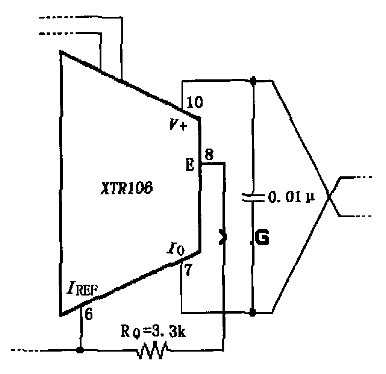
The circuit has been simplified due to the cancellation of an external transistor. The connection between the emitter terminals of the original external transistor and a 3.3k resistor will be removed, as this change has led to a decrease...