
Single op amp oscillator

The circuit operates by utilizing the properties of the Schmitt trigger to introduce hysteresis into the voltage levels, which helps in creating a stable output signal even with noisy or slow input signals. The integrator function, provided by the op-amp, converts the input voltage into a ramp signal, which is then fed into the Schmitt trigger.
The RC network, consisting of a resistor and capacitor, determines the time constants for both charging and discharging phases. During the charging phase, the capacitor voltage rises exponentially until it reaches the upper threshold of the Schmitt trigger, causing the output to switch states. When the output transitions, the capacitor begins to discharge, and closing switch SWI shortens the discharge path, effectively reducing the time constant and allowing the capacitor to discharge rapidly.
The resulting square wave produced by the circuit has a duty cycle defined by the ratio of the time the output remains high (mark) to the time it remains low (space). With a 10:1 mark-to-space ratio, the output is high for a shorter duration compared to its low state, making this circuit suitable for applications requiring specific timing sequences or pulse generation. The design is compact and efficient, leveraging the characteristics of the op-amp to produce a reliable square wave output.This circuit has a Schmitt trigger and integrator built around one op amp. Timing is controlled by the RC network. Voltage at the inverting input follows the RC charging exponential within the upper and lower hysteresis levels. By closing the switch SWI, the discharge time of the capacitor becomes ten times as fast as the rise time
Thus a square wave with an 10:1 mark space ratio is generated.
Related Circuits
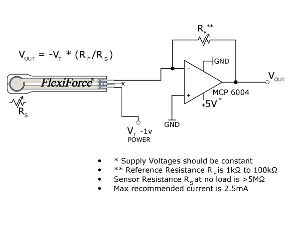
The FlexiForce sensor functions as a force-sensing resistor within an electrical circuit. When the sensor is not under load, its resistance is significantly high. Upon the application of force, this resistance decreases. The resistance can be measured by connecting...
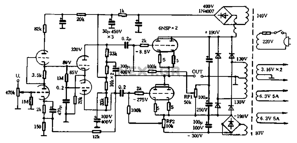
The 6N5P is a low resistance tube with an output impedance of 400 ohms, utilized in a parallel push-pull configuration. The output impedance of a single tube half can be further reduced when employing two or three tubes in...
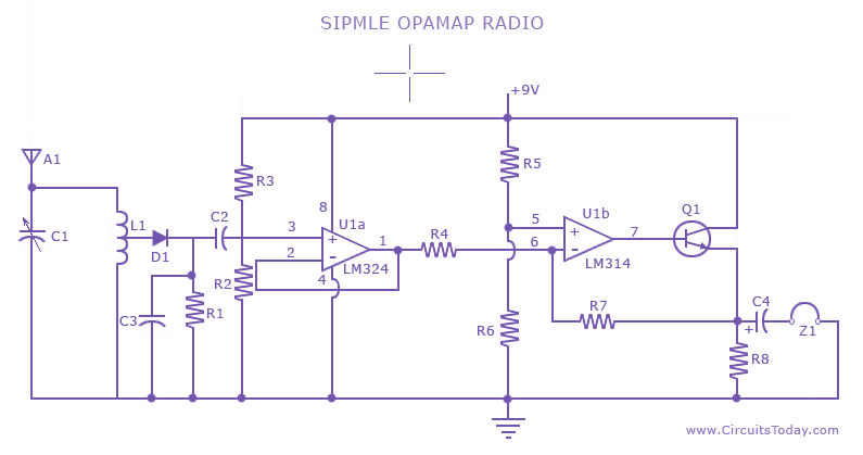
A low-cost, simple radio circuit schematic using an operational amplifier. This radio circuit diagram consists of a sensitive audio amplifier that receives strong signals. The presented radio circuit schematic utilizes an operational amplifier (op-amp) to create a cost-effective and straightforward...
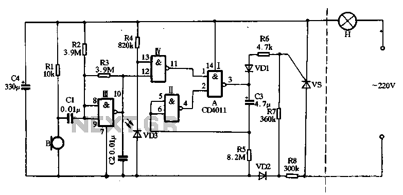
The main circuit utilizes a two-input NAND gate composed of four digital integrated circuits. This includes a NAND gate microphone amplifier circuit, a light control mechanism using an "AND gate," and a monostable delay control circuit formed by NAND...
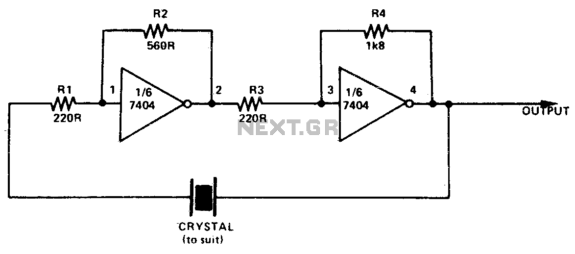
This simple and inexpensive crystal oscillator consists of one-third of a 7404 IC, four resistors, and a crystal. The inverters are biased into their linear regions by resistors R1 to R4, while the crystal provides the necessary feedback. Oscillation...
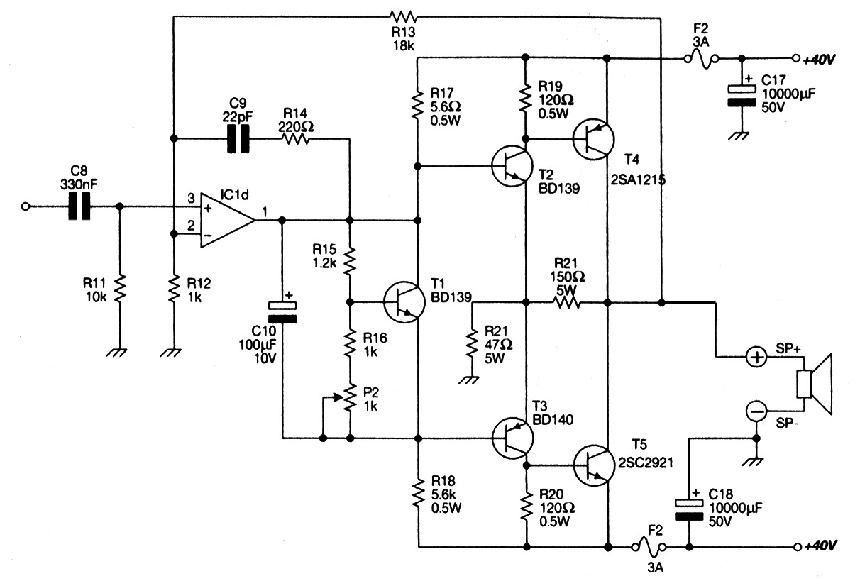
Main Power Amplifier OCL 100 watt using MJ802 and MJ4502 transistors. It is designed to provide strong bass and bold treble, making it suitable for various applications such as parties or home theater systems. This Class AB amplifier delivers...