
Multi-spark for Electronic Ignition

1. First spark doesn’t match exactly with the moment of breaking points; so, it has an aleatory delay toward this. This is equivalent to an aleatory modification of ignition advance, which will lead to non-uniform run of engine.
2. At high rpm range, the time between two impulses of multi-spark device can become comparable with the time between breaker-points impulses; this shall lead to an unstable operation of engine, with trepidations and knockings. To avoid this trouble, it is necessary to switch-off the multi-spark device when rpm of engine exceeds a certain value. With these in mind, a device is described forwards. Shaping block has the role to provide fixed length impulses (2 mS) at each breaker-points opening. In this way, false impulses which appear due to contacts vibrations are eliminated. In multi-spark module, during 2 mS interval, a sequence timer (a counter with decoded outputs) accomplishes the initialization of circuits. When impulse BP disappears, the gate P2 is opened and the counter N1 receives impulses with 1 mS period, from clock generator. This 8 bits counter measures, in fact, the duration between two breaker-points impulses. It can count maximum 255 impulses, each having 1 mS (this corresponds to 120 rpm, far below the free running speed). At next BP impulse, P2 closes and the counting stops. The number stored inside N1 is the time length between two BP impulses.
The sequence timer copies the number stored in N1 to N2, after which it resets counter N1. When BP becomes low level, N1 restarts the counting. At the same time, the up/down counter N2 starts counting the impulses having 0.5 mS period, which come via gate P1. It counts down, but with double speed. In this way, the counter N2 reaches 0 after T/2 time. The counter N4 and gate P5 generate the impulses for supplementary sparks (2 mS length). This counter works only if INH signal is at low level. The flip-flop FF1 marks the interval T/2 in which supplementary sparks will be generated. It is reset when N2 reaches 0. The gates P3 and P4 unlock the flip-flop and start supplementary sparks. Also, these gates switch-off the multi-spark function when engine speed limit is reached (in this case, ~ 2000 rpm). At about 2000 rpm, the time length between two BP impulses is 15 mS. The shaped impulse triggers directly the EID and acts as START impulse for the multi-spark module. If the engine speed is under the speed limit, the module will generate a series of supplementary impulses that, through an OR gate, will generate supplementary sparks by EID. When the speed limit is reached (for example, 2000 rpm), supplementary impulses stop at the module output, thus no supplementary sparks will be generated.
The multi-spark ignition system is designed to enhance engine performance by improving combustion efficiency and reducing emissions. The architecture includes several critical components: a shaping block for impulse generation, a sequence timer for counting and timing operations, and various counters (N1, N2, N4) for managing the timing of ignition sparks. The use of flip-flops and gates ensures precise control of the ignition timing and the modulation of supplementary sparks based on engine speed.
The shaping block is essential for ensuring that only clean, fixed-length impulses are sent to the ignition system, mitigating the effects of contact bounce. The sequence timer initiates the ignition sequence and manages the timing of the supplementary sparks, while the counters play a crucial role in determining the intervals between ignition events. The system is designed to be responsive to the engine's operational state, automatically disabling the multi-spark function at higher RPMs to maintain stability and prevent engine knock.
Overall, this multi-spark ignition system represents a sophisticated approach to improving engine performance, particularly in challenging operating conditions, and it leverages advanced timing and control techniques to optimize combustion.Multi-spark ignition is very useful especially in the case of startings at low temperature and at low rpm range. Basic idea, is to apply to spark plugs instead of only one spark, a spark-burst” having big energy. In this case, combustion of air/fuel mixture is much better and the emissions are more reduced. In addition, through burning improvement, the consumption of fuel can be reduced. Special literature abounds in multi-spark EID schematics. These have in common the fact, as the breaker-points don’t control directly EID, but an oscillator, which will generate a succession of impulses, and these impulses shall command EID. This aproach has two major deficiencies: 1. First spark doesn’t match exactly with the moment of breaking points; so, it has an aleatory delay toward this.
This is equivalent to an aleatory modification of ignition advance, which will leads to non-uniform run of engine. 2. At high rpm range, the time between two impulses of multi-spark device can become comparable with the time between breaker-points impulses; this shall lead to an unstable operation of engine, with trepidations and knockings.
To avoid this trouble, is necessary to switch-off the multi-spark device when rpm of engine exceeds a certain value. With these in mind, I imagined the device described forwards. Shaping block has the role to provide fixed length impulses (2 mS) at each breaker-points opening. In this way are eliminated the false impulses which appear due contacts vibrations. In multi-spark module, during 2 mS interval, a sequence timer (a counter with decoded outputs) accomplishes the initialization of circuits (full operations will be detailed later).
When impulse BP disappears, the gate P2 is opened and the counter N1 receives impulses with 1 mS period, from clock generator. This 8 bits counter measures, in fact, the duration between two breaker-points impulses. It can count maximum 255 impulses, each having 1 mS (see the table, this correspond to 120 rpm, far below the free running speed !).
At next BP impulse, P2 close and the counting stop. The number stored inside N1 is in fact the time length between two BP impulses. The sequence timer copy” the number stored in N1 to N2, after this resets counter N1. When BP becomes low level, N1 restarts the counting. In the same time, the up/down counter N2, starts counting the impulses having 0.5 mS period, which comes via gate P1. It counts down, but with double speed. In this way the counter N2 reach to 0” after T/2 time. The counter N4 and gate P5 makes the impulses for supplementary sparks (2 mS length). This counter works only if INH signal is at low level. The fip-flop FF1 marks” the interval T/2 in which will be generated supplementary sparks. It is reseted when N2 reach 0”. The gates P3 and P4 unlock the flio-flop and start supplementary sparks. Also, these gates switch-off the multi-spark function when engine speed limit is reached (in this case, ~ 2000 rpm).
How works this ? In the upper table we can see at about 2000 rpm, the time length between two BP impulses is 15 mS. As shown in drawing, shaped impulse triggers directly the EID and act as START impulse for multi-spark module. If rpm of engine is under speed limit, the module will generate a series of supplementary impulses that, through an OR gate, will generate supplementary sparks by EID.
When speed limit is reached (for example, 2000 rpm), supplementary impulses stops at module output, thus no supplementary sparks will be generated. 🔗 External reference
Related Circuits
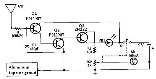
This ion detector circuit is designed to sense static charges and free ions present in the air. It is capable of detecting the presence of free ions, static electricity, or high voltage leakage. The project utilizes a short whip...
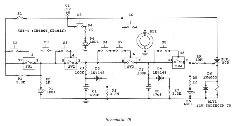
Digital IC, Electronic Lock This is an electronic code lock that can function as a door latch or ignition key. The operation is somewhat complex, which contributes to the appeal of the circuit. The electronic code lock utilizes a digital...
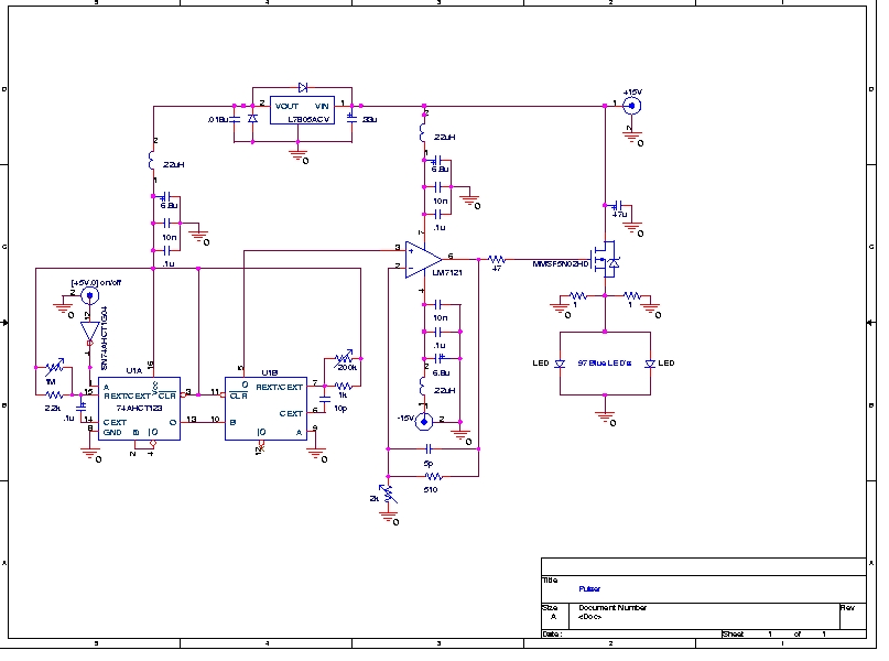
A Prototype Sample and Hold Circuit - The original concept for the veto front-end amplifiers was to continuously sample the input pulse height and maintain the pulse height for any pulses exceeding a low voltage threshold (approximately 10 mV)....
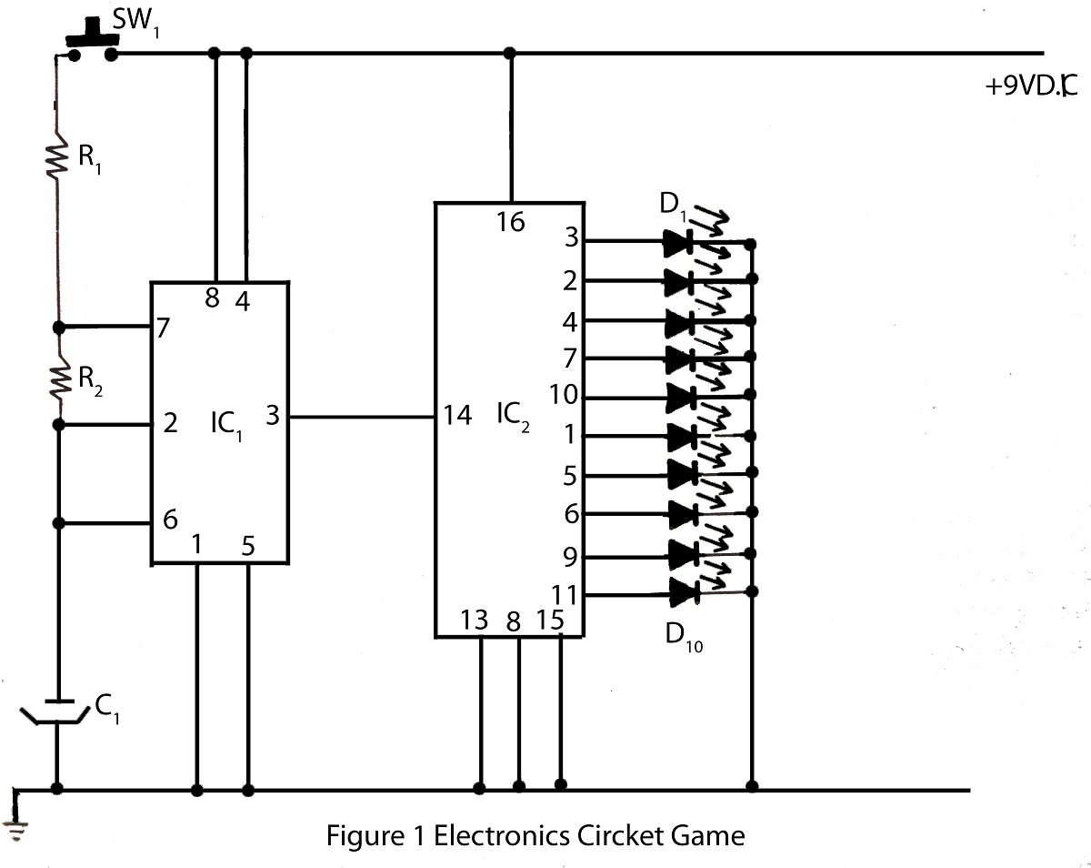
The electronics cricket game circuit presented on this website is a straightforward and easy-to-build circuit diagram for an electronics cricket project, as well as various other game projects. The electronics cricket game circuit typically consists of several key components that...

This circuit utilizes a CMOS integrated circuit to perform dual functions. The first two inverters serve as a digital audio oscillator, while the third inverter functions as a low-gain linear audio amplifier. The frequency of the oscillator increases with...
The Elect. Sel. 8 is a simple circuit, with a choice of 8 sources of any sort, of 8 independent switches. Each switch corresponding with a relay for example the switch S1 activates the RL1 etc. The uses of...