
8 way electronic selector / switch

Part List
R1-8=10Kohms IC1=74LS374 D1-8=Led 3mm R9=470 ohms IC2=74LS27 C1-3=47nF 63V MKT R10-17= 4.7Kohms IC3=74LS10 RL1-8= 6-12V DC Relay TR1=4.7Kohms Trimmer T1-8=BC550 S1-8=Push button SW
The Elect. Sel. 8 circuit functions as a source selector, utilizing eight independent switches to control eight relays. Each switch (S1 to S8) corresponds to a relay (RL1 to RL8), allowing the user to select one of eight different sources or signals. This setup is particularly useful in applications such as audio systems, where it can be employed to choose between multiple audio inputs, or in digital circuits for selecting various control signals.
The circuit incorporates a series of resistors (R1 to R8 at 10 kΩ and R10 to R17 at 4.7 kΩ) to limit current and protect the components. The inclusion of a 470 Ω resistor (R9) is intended for LED current limiting, ensuring that the 3 mm LEDs (D1 to D8) illuminate without exceeding their maximum current ratings.
The circuit utilizes three integrated circuits (IC1, IC2, and IC3) from the 74LS family, which are known for their low power consumption and high-speed operation. Specifically, IC1 (74LS374) serves as a latch, IC2 (74LS27) functions as a NAND gate, and IC3 (74LS10) acts as a triple 3-input NAND gate. These components work together to manage the state of the relays based on the switch inputs.
Capacitors (C1 to C3) rated at 47 nF and 63V are included for decoupling and stability, ensuring that the circuit operates smoothly without voltage spikes or noise interference.
The relays (RL1 to RL8) operate at a voltage range of 6-12V DC, making them suitable for controlling various loads. The transistors (T1 to T8, BC550) are used as switches to drive the relays, providing the necessary current amplification to activate the relays when a switch is pressed.
A trimmer resistor (TR1 at 4.7 kΩ) is included for calibration purposes, allowing fine-tuning of the circuit's performance. Each switch can be designed to include an LED indicator, providing visual feedback when a particular source is selected.
Overall, the Elect. Sel. 8 circuit is a versatile and efficient solution for source selection in various electronic applications, combining simplicity with functionality. The Elect. Sel. 8 is a simple circuit, with a choice of 8 sources of any sort ,of 8 independent switches. Each switch corresponding with a relay for example the switch S1 activates the RL1 e.t.c. The uses of the circuit are quite a few, choice of entrances in a sound amplifier, choice of command, in a digital circuit etc. In each entrance a LED which may be independent, except if switches with led are used. Part List R1-8=10Kohms IC1=74LS374 D1-8=Led 3mm R9=470 ohms IC2=74LS27 C1-3=47nF 63V MKT R10-17= 4.7Kohms IC3=74LS10 RL1-8= 6-12V DC Relay TR1=4.7Kohms Trimmer T1-8=BC550 S1-8=Push button SW 🔗 External reference
Related Circuits
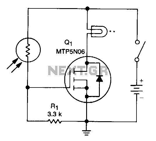
A school drama required lamps that automatically turned on and off in sync with the spotlights. The lamp switching system needed to be wireless, durable, reliable, simple, and cost-effective. With the stage and spotlights turned off, minimal light reaches...
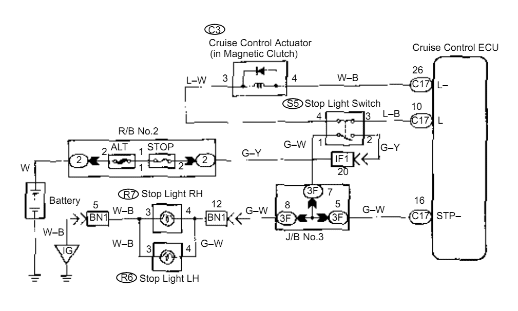
When the brake pedal is depressed, battery positive voltage normally applies through the STOP fuse and stop light switch to terminal STP of the ECU, and the ECU turns the cruise control off. A failsafe function is provided so...
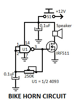
This simple electronic bicycle horn circuit utilizes a single gate from a 4093 quad 2-input NAND Schmitt trigger (U1) connected in a straightforward, low-frequency square wave configuration. The electronic bicycle horn circuit operates by generating a square wave signal that...

The BISS0001 is a high-performance integrated circuit designed for sensor signal processing. When combined with pyroelectric infrared sensors and a minimal number of external components, it forms a passive pyroelectric infrared switch. This device can automatically and quickly activate...
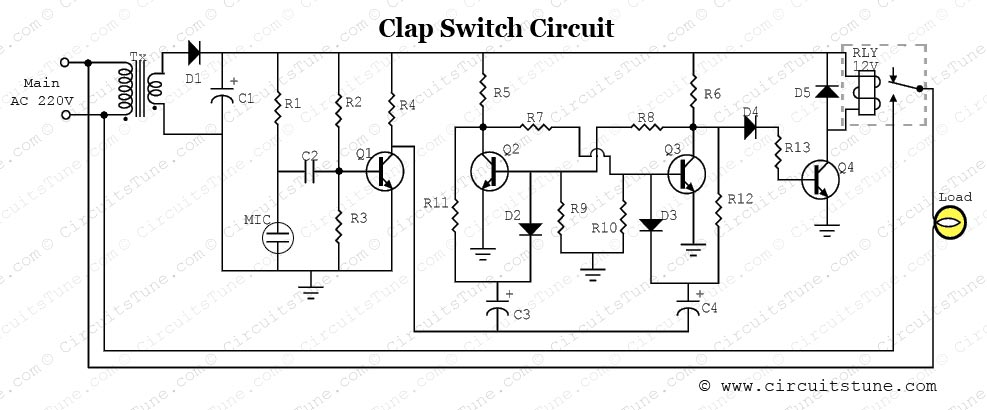
This is a simple electronic circuit for a clap switch project. It is suitable for beginner electronics learners who enjoy experimenting with new projects. The circuit can turn on or off a 220V electronic device, such as a fan...
A 1984 F-350 crew cab with a 460 engine has a malfunctioning fuel gauge and is unable to pump fuel from the front tank. The initial troubleshooting steps included replacing the switch in the dashboard and the switch on...