
Music Keyboard circuit

The astable multivibrator circuit is a type of oscillator that produces a continuous square wave output without the need for any external triggering. This circuit typically consists of two resistors, R1 and R2, and a capacitor, C1, connected to a bipolar junction transistor (BJT) or operational amplifier (op-amp).
When the circuit is powered, the capacitor charges and discharges through the resistors, creating a cycle of high and low output states. The frequency of the output waveform can be determined by the values of the resistors and the capacitor according to the formula:
\[ f = \frac{1.44}{(R1 + 2R2) \cdot C1} \]
Where:
- \( f \) is the frequency of the output signal,
- \( R1 \) and \( R2 \) are the resistances in ohms,
- \( C1 \) is the capacitance in farads.
In practical applications, the astable multivibrator can be used in timer circuits, tone generators, and clock pulses for digital circuits. The output frequency can be adjusted by changing the resistor and capacitor values, allowing for versatility in various electronic applications.
To ensure stable operation, it is important to consider the power supply voltage and the characteristics of the components used, as these will influence the performance and reliability of the circuit. Proper layout and grounding techniques should also be employed to minimize noise and interference, which can affect the frequency stability.The work of the circuit this origin frequency sound circuit model astable multi vibrator. When build the circuit suits power supply the circuit will still.. 🔗 External reference
Related Circuits
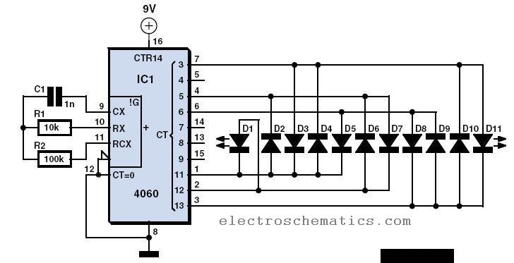
Have you already set up a Christmas tree in your house and decorated it with traditional lights? Build a couple of these LED lights to enhance the Christmas atmosphere. The project involves creating LED lights that can be used to...
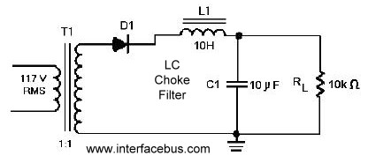
A circuit that utilizes one cycle of alternating current (AC) to produce direct current (DC). A half-wave rectifier circuit generates DC from either the positive or negative cycle of the AC input, but not both. It is important to...
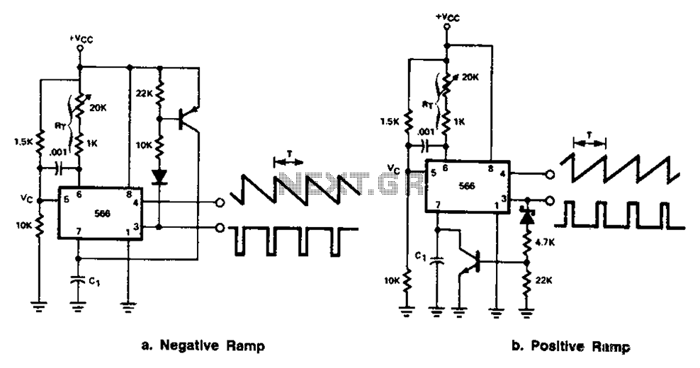
The 566 can be connected to either a positive or negative ramp generator. For a positive ramp generator, an external transistor is driven by the output pin 3. At the end of charging, C1 discharges quickly, allowing for immediate...
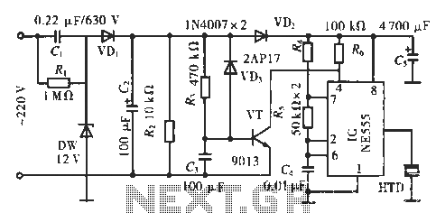
The circuit utilizes a 555 integrated circuit (IC). When an incoming call is received, 220 V AC is stepped down through resistor R1, followed by rectification using diode VD1. A voltage regulator (DW) is employed, and capacitor C2 is...

This design circuit serves as a converter utilizing the LM2623A ratio adaptive circuit to drive a digital camera motor. It generates 5 volts from input voltages that range between 1.8 and 4.5 volts. The circuit's duty cycle, while not...
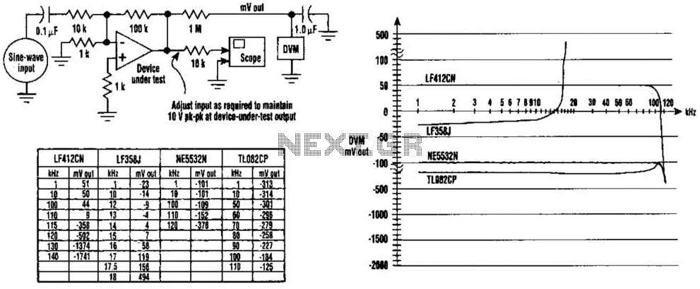
The DC values of op-amp offsets cannot always be assumed to remain constant when delivering AC outputs. No device is perfectly symmetrical in terms of maximum positive slew rate compared to maximum negative slew rate. As a result, there...