
Check For Op-Amp Dc Offset Shift Circuit

The test circuit designed to evaluate the shift in DC offset due to AC output characteristics of operational amplifiers comprises several key components. The circuit typically includes an op-amp configured in a non-inverting amplifier setup, allowing for the observation of the output signal in relation to the input. Input AC signals of varying frequencies and amplitudes are fed into the circuit. A feedback resistor network is employed to set the gain of the op-amp and ensure proper operation within the desired frequency range.
To measure the DC offset shift, a precision voltmeter is connected to the output of the op-amp. The output signal is monitored while varying the frequency of the input AC signal, which allows for the analysis of the slew rate effects on the output. The results can be recorded and plotted in a table and graph format, illustrating the relationship between the frequency, slew rate, and the observed DC offset shift for each op-amp model tested.
The circuit can be enhanced with additional features, such as a low-pass filter to isolate the DC component of the output signal, or a comparator to trigger an alert when the DC offset exceeds a predefined threshold. This comprehensive approach facilitates a deeper understanding of how different op-amps respond to varying AC conditions and highlights the importance of accounting for DC offset shifts in precision applications. The dc values of op-amp offsets can`t always be taken for granted when delivering ac outputs. No device is ever exactly symmetrical for maximum positive slew rate versus maximum negative slew rate. Consequently, there is always some range of output slew rates in which the device used limits in one direction more severely than in the other.
What results in rectification of the ac signal and an apparent shift of the dc offset. This test circuit can check for the shift phenomenon. The accompanying table and graph illustrate the results obtained for four devices, all of different types. As frequency and slew rate are increased, the effect can be either relatively abrupt (LF412CN and NE55532N) or relatively gradual (LF358J and TL0820P).
Related Circuits
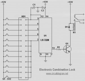
This circuit diagram represents a simple electronic combination lock utilizing the IC LS7220. The circuit is designed to activate a relay for controlling any device (on and off) each time a specific combination of four digits is entered. It...
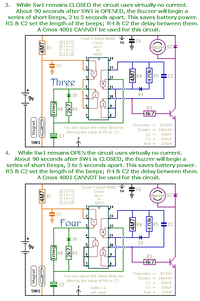
This is a collection of compact, self-sufficient alarm circuits designed for low standby current, making them ideal for battery operation. Some circuits are activated by normally-open and normally-closed switches, while others respond to variations in light or temperature. This...
A high-input-resistance op-amp, a bridge rectifier, a microammeter, and a few other discrete components are all that are required to realise this versatile circuit. This circuit can be used for measurement of dc, ac rms, ac peak, or ac...
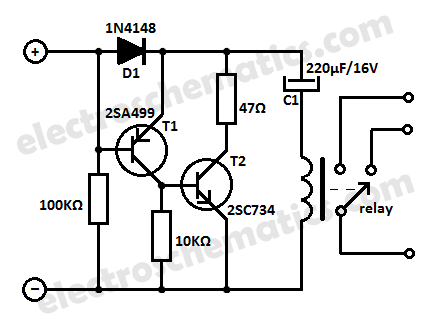
Protect your equipment with this compact 12V time delay relay circuit. The SMPS-based power supply of modern electronic devices is susceptible to voltage spikes. This 12V time delay relay circuit is designed to safeguard sensitive electronic devices by providing a...
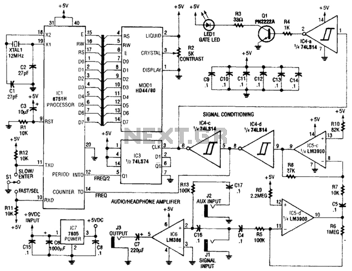
Perfect Pitch, which is based on the 8751 microprocessor, is an affordable and straightforward instrument tuner and frequency counter that features a built-in headphone amplifier and a visual metronome. Perfect Pitch converts the audio signal from an instrument into...
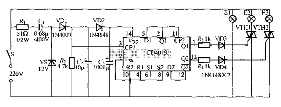
Figure 296 illustrates a control circuit that utilizes a switch (S) to manage three lamps (E1, E2, and E3) in a lighting system, suitable for controlling a chandelier in a living room. When the switch is off, all lights...