
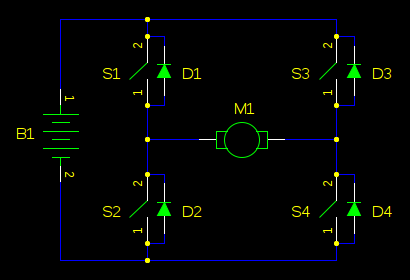
N-Channel H-bridge Motor Drive

The N-Channel H-bridge motor drive circuit is designed to control the direction and speed of a DC motor using low voltage. The circuit consists of four N-channel MOSFETs arranged in an H-bridge configuration, which allows for bidirectional control of the motor. When the MOSFETs are switched on and off in a specific sequence, the polarity of the voltage applied to the motor can be reversed, enabling forward and reverse operation.
In this configuration, two pairs of N-channel MOSFETs are used: one pair connected to the high side and the other to the low side of the motor. The gates of the MOSFETs are driven by a microcontroller or a dedicated motor driver IC, which provides the necessary control signals. The use of N-channel MOSFETs is advantageous due to their lower on-resistance compared to P-channel MOSFETs, resulting in higher efficiency and reduced heat generation in the circuit.
To ensure safe operation, the circuit may include additional components such as flyback diodes to protect against voltage spikes generated when the motor is turned off. Additionally, current sensing resistors can be incorporated to monitor the motor's current draw, allowing for feedback control and protection features, such as overcurrent shutdown.
The design is suitable for applications where low voltage operation is required, making it ideal for battery-powered devices or small robotics. The simplicity of the H-bridge design allows for easy integration into various projects, providing reliable motor control with minimal complexity.The following circuit shows about N-Channel H-bridge Motor Drive Circuit Diagram. Features: low voltage motor drives, in an N-channel .. 🔗 External reference
Related Circuits
In motor control circuits, precautions must be taken to prevent the motor from feeding back into the power supply, which can cause the supply voltage to rise and potentially damage components. However, unless an external force is accelerating the...
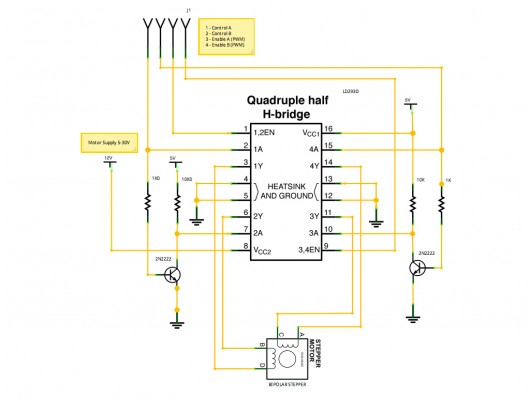
A stepper motor controller based on schematics available on the Arduino website. Initially, a two-pin configuration was attempted for a bipolar stepper motor, but it did not function as expected, especially with the library provided on the site. The...
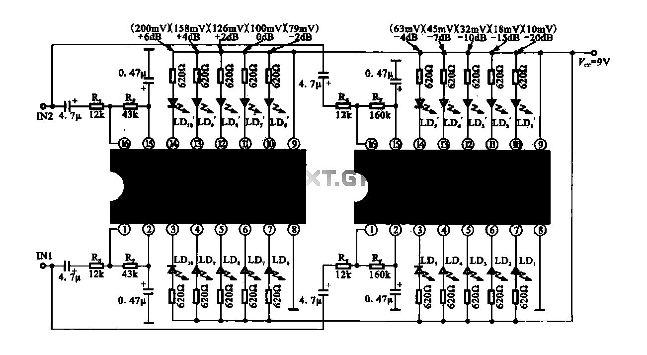
The circuit consists of dual drive integrated circuits (ICs) utilized in a 10 LED level meter configuration. The schematic features two TLM8101 driver ICs, which can be employed as alternatives. The 10 LED level meter circuit is designed to provide...
The design of a PAR 38 LED spotlight focuses on delivering practical LED lighting systems that meet performance expectations by reducing power consumption, extending lifespan, and enhancing overall efficiency. The PAR 38 LED spotlight is a widely used lighting solution...

The M-88L70 is a complete DTMF receiver that combines both band-split filter and decoder functions into a single 18-pin DIP or SOIC package. It is manufactured using CMOS process technology, which allows for low power consumption (maximum 18 mW),...
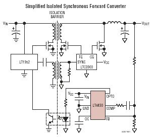
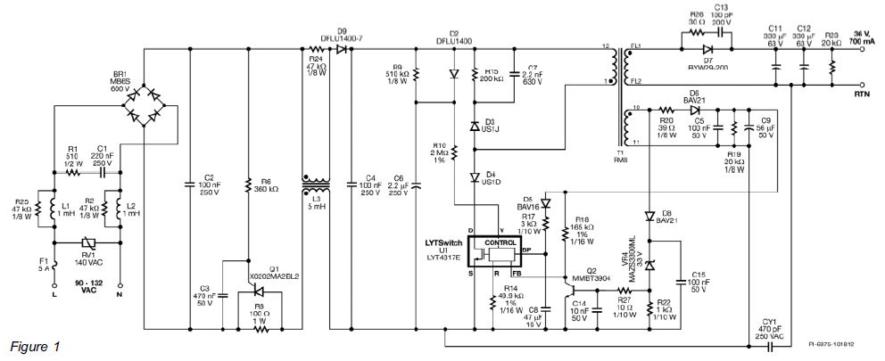
The LT4430 drives the opto-coupler that crosses the galvanic barrier in an isolated power supply. The IC contains a precision-trimmed reference, a high bandwidth error amplifier, an inverting gain of 6 stage to drive the opto-coupler, and unique overshoot...