
N5ESEs QRP Dummy Load With Built-in RF Detector

The described dummy load circuit is an effective solution for low-power HF applications, particularly in experimental or hobbyist settings. The use of copper pipe not only enhances thermal management but also provides a robust physical structure for the assembly. The built-in RF detector is a significant feature, allowing users to measure output power directly and accurately. The choice of resistors is critical; the 100-ohm resistors are selected for their power rating and tolerance, ensuring reliable performance under continuous operation.
The construction involves careful assembly of the printed circuit board (PCB), where the resistors are arranged in parallel and series configurations to achieve the necessary equivalent resistance. The PCB layout is designed to facilitate efficient heat dissipation, and the use of teflon-insulated wire is essential to prevent insulation failure due to heat generated by the resistors.
Safety considerations are paramount; the dummy load should be placed in a non-flammable area, away from materials that could catch fire. Users should also be aware of the heat generated during operation, especially when driving the load with higher power levels. The design's SWR performance indicates that it is suitable for a wide range of HF applications, ensuring minimal signal reflection and efficient power transfer.
In summary, this dummy load circuit is a practical, low-cost solution for amateur radio enthusiasts and provides essential features for power measurement and safe operation. Proper construction techniques and materials selection are crucial to achieving the desired performance and safety standards.This is yet another variation on the "parallel resistor" dummy load. [Go -here- for a discussion on dummy load theory]. This is another one I built during my infatuation with copper pipe. It`s suitable for QRP HF operation of 5-watts or less average power, and should be adequate for continuous operation at that level. It`s light and compact, about 5-inches in length overall. This one is unique in that it has a built-in RF detector, with scaling, that may be used with your DC Voltmeter to measure power. Dummy loads dissipate energy by generating heat. Heat generated in a small space translates to temperature rise, and temperatures can be hot enough (under the right circumstances) to burn people and ignite adjacent materials.
Because of the thermal mass of the dummy load and its enclosure, that heat can stay around for a long time. Always locate your dummy load in a safe place, where there is no chance that it will burn people or catch something on fire.
The 1/2" copper pipe provides a convenient, compact form factor, is an excellent shield, and helps to dissipate heat to the outside world. Copper end-caps, available at most any hardware or plumbing supplier, provide a means of mounting the two UG-1094 BNC jacks and closing the unit.
This version uses 8 each 100-ohm 1-watt 5% metal-oxide resistors, available from Radio Shack for a mere 25-cents each (RS 271-152). All the detector parts (yes, all three of them, a 0. 01 capacitor, a 4. 7-Meg resistor, and a 1N34A diode) are also available at Radio Shack. You would be hard-pressed to spend much more than $5-6 dollars on this project. The resistors are good through the HF range, but don`t do particularly well at VHF. Here`s a schematic: We`ll fabricate a printed-circuit board from scrap double-sided copper board, cut to 1/2 x 2-inches, and grooved to form pads on each side, as shown in the layout below.
On the top side, we`ll mount 4 of the 8 resistors, and on the bottom side we mount the remainder. Simply tack-solder the resistors to the board. Where required to connect the resistors, we drill a small hole through the board, and solder a wire in place top-to-bottom. On the top side, we end up with a 100-ohm, 4-watt equivalent resistor (a pair of parallel 100 ohm resistors makes 50 ohms, and two pairs in series make 100-ohms).
When we join the top and bottom in parallel, our equivalent resistance is 50-ohms (two 100-ohm quads in parallel). Mount a UG-1094 BNC Jack in each of the two copper end-caps. then, connect the pc board assembly directly to the center post of the BNC connector, soldering same.
Make all other interconnections with teflon-insulated wire. DON`T SUBSTITUTE OTHER INSULATIONS! Sorry, I know teflon wire is tough to find, but other insulation types will almost certainly fail when the resistors get hot. Wrap the entire pc-board assembly in teflon tape (often called plumber`s tape, available at any hardware store.
DO NOT use other types of tape (they will melt!). Next, we slide a short piece of 1/2-inch copper tubing over the assembly, slipping it into the BNC/end-cap. At this point, an ohmmeter should verify 50-ohms. Finally, solder the detector output wires to the second BNC, and mount the other end-cap to close and shield the unit.
Drill and tap a screw into both end caps to connect the shield both electrically and mechanically. When supplied RF power for an extended time, this dummy load can get quite warm, even with just 5 watts. Be aware, and plan for it. (Read the "WARNING!" above). My version has an SWR of 1:1 throughout the HF range (DC to 30 MHz). Measuring power is easy, and accurate if the detector`s resistor is sized to work with your DC Voltmeter`s input impedance.
Read the DC Voltage, square it, and divide by 50. Example: we read 10 Volts, which is 10 * 10 / 50 = 2 watts. 🔗 External reference
Related Circuits
Tools that feature the equivalent of a professional, easy-to-use, cheaper, and, more importantly, safe for use. They are designed for checking and identifying AC voltages of 220 Volt or 120 Volt. The tools mentioned are essential for ensuring electrical safety...
Men, in particular, appreciate the convenience of television remote controls, which can often lead to frustration for their female partners. Men seem to have a desire to understand what... The initial statement highlights a common dynamic in household technology usage,...
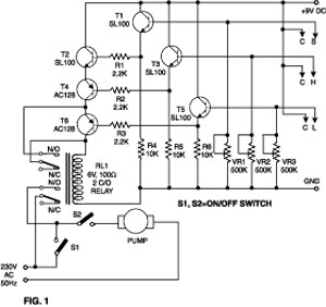
This simple water detector circuit utilizes alternating voltage to prevent the corrosion of the electrodes. It is straightforward to construct and employs N1 as a trigger Schmitt gate that generates the AC signal. When an electrical conductor, such as...
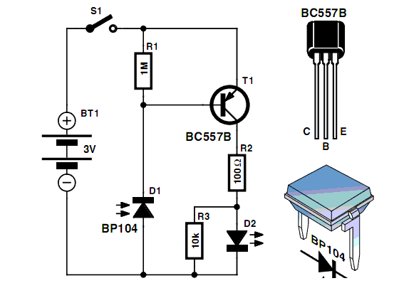
A simple proximity detector electronic project can be designed using this schematic circuit. This project utilizes a tone decoder integrated circuit (NE567) that provides a signal with a frequency of approximately 100 kHz. When an object is placed near...
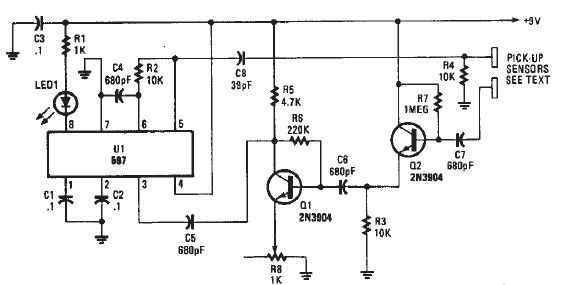
This detector circuit is sensitive to low-frequency electromagnetic radiation and can detect hidden wiring or the field around a transformer. The pickup is achieved using a radial type inductor, which serves as a probe that responds effectively to low-frequency...

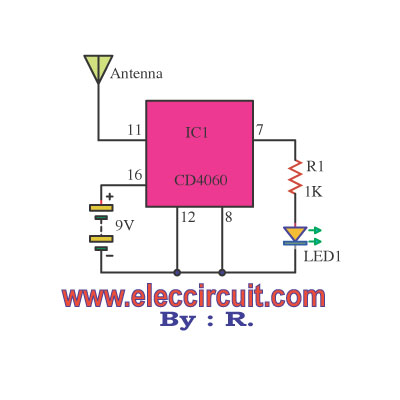
This compact mobile transmission detector is capable of sensing the presence of an active mobile phone from a distance of 1.5 meters. It can be utilized to prevent mobile phone usage in examination halls, confidential areas, and similar environments....