
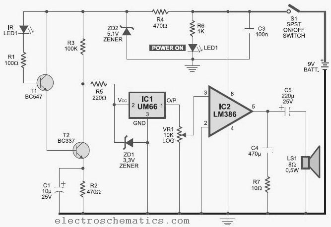
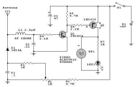
Mobile Bug Detector

The circuit employs a 0.22 µF disk capacitor (C3) to capture RF signals from mobile phones. The capacitor's lead length is set at 18 mm with an 8 mm spacing between the leads to achieve the desired frequency response. This disk capacitor, along with its leads, functions as a small gigahertz loop antenna to collect RF signals. The operational amplifier IC CA3130 (IC1) is incorporated in the circuit as a current-to-voltage converter, with capacitor C3 connected between its inverting and non-inverting inputs. This CMOS version of the op-amp utilizes gate-protected p-channel MOSFET transistors at the input, providing high input impedance, low input current, and rapid performance. The output CMOS transistor can swing the output voltage to within 10 mV of either supply voltage terminal.
Capacitor C3, in conjunction with the lead inductance, acts as a transmission line that intercepts signals from the mobile phone. It creates an electric field, stores energy, and transfers this energy as a minute current to the inputs of IC1, thereby disrupting the balanced input of the amplifier and converting the current into a corresponding output voltage. Capacitor C4, along with high-value resistor R1, stabilizes the non-inverting input to facilitate a high output swing. Resistor R2 provides a discharge path for capacitor C4, while feedback resistor R3 raises the inverting input when the output is high. Capacitor C5 (47pF) is connected across the strobe (pin 8) and null (pin 1) inputs of IC1 to achieve phase compensation and gain control, optimizing the frequency response.
When C3 detects a mobile phone signal, the output of IC1 alternates between high and low states according to the signal frequency, as indicated by LED1. This output triggers monostable timer IC2 through capacitor C7. Capacitor C6 maintains base bias for transistor T1 to ensure rapid switching. Low-value timing components R6 and C9 create a very short time delay to minimize audio nuisance. The circuit should be assembled on a general-purpose PCB, compactly enclosed in a small container, such as an old mobile phone case. Care should be taken to maintain the specified lead length of 18 mm and lead spacing of 8 mm for capacitor C3, soldering it in an upright position with equal spacing. The performance can be fine-tuned by adjusting the lead length of C3 to achieve the desired frequency response. A short telescopic antenna may be utilized, and a miniature 12V battery from a remote control, along with a small buzzer, can be employed to create a pocket-sized device. This unit will provide a warning indication if a mobile phone is used within a 1.5-meter radius.This handy, pocket-size mobile transmission detector can sense the presence of an activated mobile phone from a distance of one-and-a-half metres. So it can be used to prevent use of mobile phones in examination halls, confidential rooms, etc. It is also useful for detecting the use of mobile phone for spying and unauthorised video transmission.
T he circuit can detect both the incoming and outgoing calls, SMS and video transmission even if the mobile phone is kept in the silent mode. The moment the bug detects RF transmission signal from an activated mobile phone, it starts sounding a beep alarm and the LED blinks.
The alarm continues until the signal transmission ceases. An ordinary RF detector using tuned LC circuits is not suitable for detecting signals in the GHz frequency band used in mobile phones. The transmission frequency of mobile phones ranges from 0. 9 to 3 GHz with a wavelength of 3. 3 to 10 cm. So a circuit detecting gigahertz signals is required for a mobile bug. Here the circuit uses a 0. 22 µF disk capacitor (C3) to capture the RF signals from the mobile phone. The lead length of the capacitor is fixed as 18 mm with a spacing of 8 mm between the leads to get the desired frequency.
The disk capacitor along with the leads acts as a small gigahertz loop antenna to collect the RF signals from the mobile phone. Op-amp IC CA3130 (IC1) is used in the circuit as a current-to-voltage converter with capacitor C3 connected between its inverting and non-inverting inputs.
It is a CMOS version using gate-protected p-channel MOSFET transistors in the input to provide very high input impedance, very low input current and very high speed of performance. The output CMOS transistor is capable of swinging the output voltage to within 10 mV of either supply voltage terminal.
Capacitor C3 in conjunction with the lead inductance acts as a transmission line that intercepts the signals from the mobile phone. This capacitor creates a field, stores energy and transfers the stored energy in the form of minute current to the inputs of IC1.
This will upset the balanced input of IC1 and convert the current into the corresponding output voltage. Capacitor C4 along with high-value resistor R1 keeps the non-inverting input stable for easy swing of the output to high state.
Resistor R2 provides the discharge path for capacitor C4. Feedback resistor R3 makes the inverting input high when the output becomes high. Capacitor C5 (47pF) is connected across strobe` (pin 8) and null` inputs (pin 1) of IC1 for phase compensation and gain control to optimize the frequency response. When the mobile phone signal is detected by C3, the output of IC1 becomes high and low alternately according to the frequency of the signal as indicated by LED1.
This triggers monostable timer IC2 through capacitor C7. Capacitor C6 maintains the base bias of transistor T1 for fast switching action. The low-value timing components R6 and C9 produce very short time delay to avoid audio nuisance. Assemble the circuit on a general-purpose PCB as compact as possible and enclose in a small box like junk mobile case. As mentioned earlier, capacitor C3 should have a lead length of 18 mm with lead spacing of 8 mm. Carefully solder the capacitor in standing position with equal spacing of the leads. The response can be optimized by trimming the lead length of C3 for the desired frequency. You may use a short telescopic type antenna. Use the miniature 12V battery of a remote control and a small buzzer to make the gadget pocket-size. The unit will give the warning indication if someone uses mobile phone within a radius of 1. 5 meters. 🔗 External reference
Related Circuits
This infrared detector is capable of detecting the presence of modulated infrared signals in its vicinity from various electronic sources, such as an IR handheld remote. The infrared detector operates by utilizing a photodetector that is sensitive to infrared light....
Tools that feature the equivalent of a professional, easy-to-use, cheaper, and, more importantly, safe for use. They are designed for checking and identifying AC voltages of 220 Volt or 120 Volt. The tools mentioned are essential for ensuring electrical safety...
This do-it-yourself lightning detector circuit is a highly sensitive continuous electricity detector that can provide an early warning of approaching storms from inter-cloud discharges prior to an earth-to-sky lightning strike occurring. An aerial antenna made of a short length...
The metal detector circuit comprises several key components, including a power circuit, a sine wave oscillator, a PLL (phase-locked loop) circuit, and a hybrid amplifying circuit. The power circuit is made up of batteries GBI and GB2, filter capacitors...
This electronic RF detector project is designed using common transistors and a few standard electronic components. The RF detector responds to RF signals below the standard broadcast band and well over 500 MHz, providing both visual and audible indications...
The frequency detection circuit utilizes a transistor line, adjustable via a preset switch K1, to convert capacitance and frequency measurements. The K1 switch is positioned to detect capacitance. The circuit comprises components including a 555 timer, resistors R8 to...