
ne555 police siren circuit

The described police siren circuit employs two NE555 timer ICs to generate a distinctive sound pattern reminiscent of an emergency vehicle siren. The first timer, IC1, is set up as a slow astable multivibrator, oscillating at a frequency of about 20Hz. This frequency is characterized by a 50% duty cycle, meaning the output signal is high for half the period and low for the other half. The output from IC1 serves as a control signal for the second timer, IC2.
IC2 is configured to operate at a much higher frequency of approximately 600Hz. This higher frequency produces a rapid pulsing sound, which is essential for achieving the siren effect. By connecting the output of IC1 to pin 5 (the control voltage input) of IC2, the oscillation frequency of IC2 is modulated. As IC1's output varies, it influences the behavior of IC2, allowing the siren sound to rise and fall in pitch, which is a critical feature of a typical police siren.
The power supply for this circuit can range from 6 to 15 volts DC, making it versatile for different applications. To further enhance the loudness of the output, a power amplifier can be connected to the output of IC2. This addition amplifies the sound produced, making it suitable for use in various scenarios where a loud siren sound is necessary.
In summary, this circuit design effectively utilizes the NE555 timer IC in a dual configuration to create a police siren sound, with the ability to adjust volume through external amplification. The interaction between the two astable multivibrators enables a dynamic output that simulates the auditory characteristics of emergency vehicle sirens.A lot of electronic circuits using NE555 timer IC Here is the circuit diagram of a police siren based on NE55 timer IC. The circuit uses two NE555 timers ICs and every of them are wired as astable multivibrators. The circuit will be powered from something between 6 to 15V DC and is fairly loud. By connecting an extra power amplifier at the output you can further increase the loudness. IC1 is wired as a slow astable multivibrator operating at around 20Hz @ 500th duty cycle and IC2 is wired as quick astable multivibrator operating at around 600Hz. The output of first astable mutivibrator is connected to the control voltage input (pin5) of IC2. This makes the output of IC2 modulated by the output frequency of IC1, giving a siren effect. In easy words, the output frequency of IC2 is controlled by the output of IC1. 🔗 External reference
Related Circuits
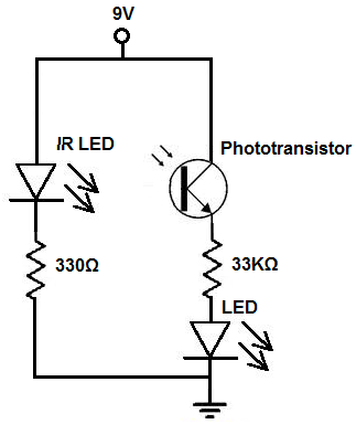
There are two methods to construct a proximity detector. The first method involves mounting the infrared (IR) LED and the phototransistor so that they face each other. In this configuration, the infrared light emitted by the IR LED is...
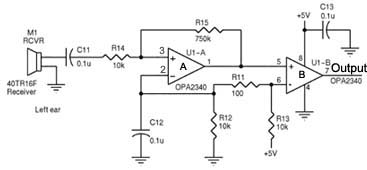
Assistance is required regarding the circuits provided below. The focus is on an ultrasonic receiver circuit that utilizes two ultrasonic components. The ultrasonic receiver circuit is designed to detect ultrasonic waves, typically in the frequency range of 20 kHz to...
This circuit was developed in response to requests from website visitors for a timer that can emit a beep after intervals of one, two, three minutes, and so forth, for jogging purposes. As depicted in the circuit diagram, SW1...
The circuit was designed to create an alarm system that alerts a sleeping person to prevent snoring by utilizing a vibrator instead of an audio alert. The circuit operates on the principle of detecting snoring sounds through a microphone or...
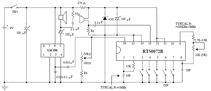
This voice changer circuit diagram is an electronic project developed using the RTS0072B single-chip CMOS LSI, specifically designed for voice-changing applications. It can transpose or distort one voice into another by encoding the input audio signals at normal speed...

When switch SI is closed, pin 9 of operational amplifier U1 goes low, activating transistor Q1 for a predetermined duration. If switch S2 is closed during this time, transistor Q2 is activated for another predetermined duration. Resistors R1 and...