
jogging timer circuit diagram

The circuit utilizes a rotary switch (SW1) to select the desired timing interval, allowing users to customize their beep notifications according to their jogging routines. The piezo sounder serves as the auditory alert, providing a clear and attention-grabbing signal. The timing mechanism is typically implemented using a combination of resistors, capacitors, and possibly a microcontroller or timer IC to accurately measure the time intervals.
In position 1, the timer circuit is configured to produce a short pulse every minute, which triggers the piezo sounder to emit three distinct beeps. The timing is achieved through a resistor-capacitor (RC) network that charges and discharges at a rate corresponding to one minute. As the switch is moved to subsequent positions, the values of the resistors or capacitors may be altered to extend the timing intervals appropriately.
For example, in position 2, the circuit is adjusted to create a two-minute delay before the sounder activates. This adjustment could involve increasing the capacitance or resistance in the timing circuit, thereby doubling the time it takes for the capacitor to charge to the threshold voltage required to activate the sounder. This method of extending the timer can be replicated for each position on the rotary switch, culminating in a maximum timing interval of nine minutes in position 9.
The design of this timer circuit is simple yet effective, making it suitable for a variety of applications beyond jogging, such as cooking timers, reminders, or any scenario where timed auditory notifications are beneficial. The use of a piezo sounder ensures low power consumption, making the circuit efficient for prolonged use, especially in portable applications. Overall, this timer circuit is a practical solution for users seeking a customizable timing mechanism with auditory feedback.This circuit was developed since a number of visitors of this website requested a timer capable of emitting a beep after one, two, three minutes and so on, for jogging purposes. As shown in the circuit diagram, SW1 is a 1 pole 9 ways Rotary Switch. Setting the switch in position 1, the Piezo sounder emits three short beeps every minute. In position 2 the same thing happens after a 2 minutes delay, and so on, reaching a maximum interval of 9 minutes in position 9..
🔗 External reference
Related Circuits
Solar battery charger schematic and description. This solar battery charger circuit is capable of charging a 12V lead-acid battery or sealed lead-acid (SLA) battery. The solar battery charger circuit is designed to convert solar energy into electrical energy for charging...
Circuits that utilize large value resistor and capacitor combinations tend to lack accuracy due to the wide tolerance and leakage current of polarized capacitors. A more effective approach is to implement an astable circuit in conjunction with a binary...
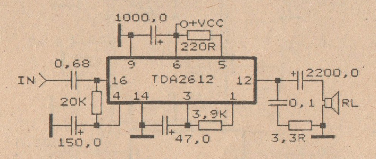
This amplifier circuit is based on the IC TDA2612 produced by Siemens. The minimum voltage required for this circuit is 10 volts, while the maximum voltage is 35 volts DC. The power output is 25 watts with a 4-ohm...
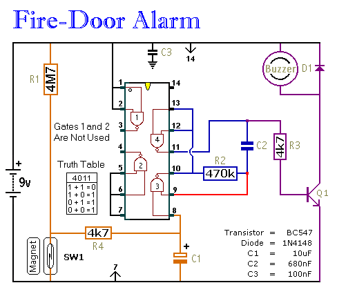
This circuit provides an alert when a door that should remain closed is left open. It is designed to be attached to a fire door, allowing normal passage. If the door remains open for more than 30 seconds, a...

The LM3915 monolithic integrated circuit can be used to design a simple audio power level meter that senses analog voltage levels and drives ten LEDs, LCDs, or vacuum fluorescent displays, providing a logarithmic 3 dB/step analog display. One pin...

Transistors Q1 and Q2, along with resistors R1 through R7, form the input balancing stage that measures the resistance between points X and Y. This stage operates as a bridge circuit, incorporating resistors R1, R2, R6, R7, and the...