
NE566 frequency modulator

The NE566 integrated circuit operates as a voltage-controlled oscillator (VCO), allowing for frequency modulation based on the input voltage. The configuration presented enables the generation of a frequency-modulated signal, where the output frequency is directly influenced by the input voltage levels.
In this circuit, Ri and R2 serve as the timing resistors that help determine the oscillation frequency. The resistor Rd is connected to the timing capacitor, which influences the charge and discharge cycles, further affecting the output frequency. The variable resistor, RP2, plays a crucial role in fine-tuning the output frequency and can be adjusted to achieve the desired modulation characteristics.
When the input terminal potential is altered, the NE566 responds by adjusting the oscillation frequency, which is a fundamental aspect of frequency modulation. This allows the circuit to be used in various applications, including communication systems where the frequency of the transmitted signal must be modulated in response to the input signal variations.
The output frequency can be monitored and measured using an oscilloscope or frequency counter to ensure it aligns with the expected modulation range. The design can be expanded with additional components, such as filters or amplifiers, to enhance performance and signal integrity, depending on the specific application requirements. Overall, the NE566 frequency modulator is a versatile component in electronic circuits, providing reliable frequency modulation capabilities.A frequency modulator configured NE566 integrated voltage-controlled oscillator shown in FIG. When the signal input terminal potential DC position, forming a cycle of constant frequency oscillation; change input terminal potential, IC output frequency of the frequency modulation circuit changes accordingly. FIG component parameter reference value, when the resistance: Ri - R2 - lOOfl. Rd - lOkZRP2 - when 50kfl, 20 to the output frequency can be about a corresponding change in 40kHz; RP2 or change the value of G, the output frequency changes accordingly.
Related Circuits
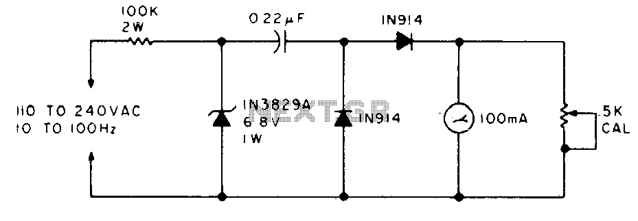
The meter will display the frequency from a power generator. Incoming sine waves are transformed into square waves by the 100K resistor and the 6.8 V zener diode. The square wave is differentiated by the capacitor, and the current...
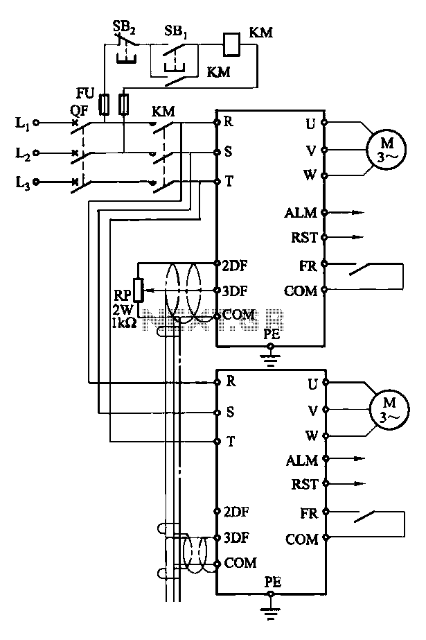
Each motor operates with an independent drive; however, only one frequency is utilized for a specific device. This setup employs a single RP potentiometer to control multiple motors in parallel. In this configuration, the circuit design allows for multiple motors to...
It consists only from Microchip PIC 16F84 cpu and LCD text module. Author states that this counter is capable metering frequencies from 400Hz to 50MHz. I used faster, 20MHz version of 16F84A-20I/P, and it managed to count 80MHz oscillator...
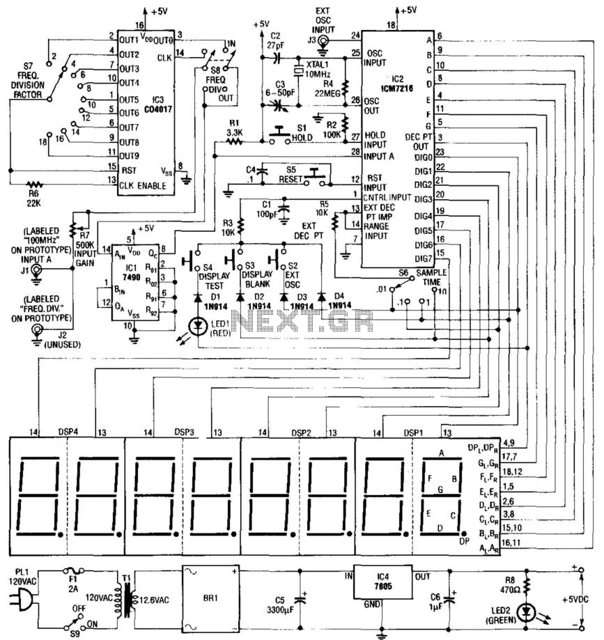
Built around an Intersil 7216 frequency counter IC, this counter has a basic range of 10 MHz, a 100-MHz prescaler, and an extra frequency divider (IC3). This divider reduces the frequency by an additional factor, as indicated on S7...
Power the frequency counter and adjust the coarse (top pot) and fine (bottom pot) controls to display zero frequency. Turn the pots counter-clockwise to achieve a zero reading. Occasionally, the counter may show only squares without digits. If this...
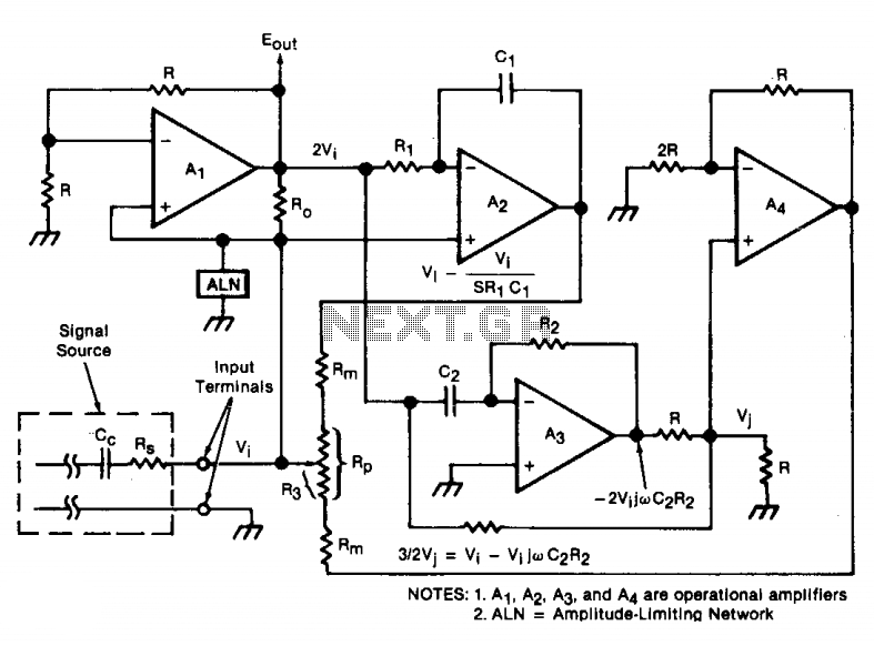
An oscillator/amplifier is resistively tunable over a wide frequency range. Feedback circuits containing operational amplifiers, resistors, and capacitors synthesize the electrical effects of inductance and capacitance in parallel between the input terminals. The synthetic inductance and capacitance, and therefore...