
A given frequency control multiple motors operating in parallel circuits

In this configuration, the circuit design allows for multiple motors to be controlled simultaneously while maintaining individual operational characteristics. Each motor drive circuit is designed to be independent, ensuring that variations in load or performance do not adversely affect the operation of other motors in the system. The single frequency signal is generated by a common oscillator circuit, which is then fed into each motor drive circuit.
The RP (rotational position) potentiometer serves as a critical component in this design, allowing for the adjustment of the signal amplitude that is sent to each motor. This enables fine-tuning of motor speed and torque characteristics while ensuring that all motors receive the same frequency signal. The potentiometer can be adjusted to change the resistance in the circuit, thereby altering the voltage supplied to the motors and allowing for synchronized operation.
The schematic for this system would typically include the following components: a power supply to provide the necessary voltage and current to the motors, an oscillator circuit to generate the frequency signal, the RP potentiometer for signal adjustment, and individual drive circuits for each motor, which may include transistors or MOSFETs for switching and amplifying the control signal. Additionally, protection components such as diodes may be included to prevent back EMF from the motors from damaging the circuit.
This design is particularly useful in applications where multiple motors need to operate in unison, such as in robotics, conveyor systems, or automated machinery, allowing for efficient and coordinated movement.Each motor with independent drive, but only one frequency for a given device, which uses the same RP potentiometer to achieve a multiple motors in parallel.
Related Circuits
The old and omnipresent NE555 can be very good at something it was not meant for: driving relays or other loads up to 200 mA. The picture shows an example circuit: if the input level rises over 2/3 of...
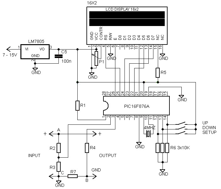
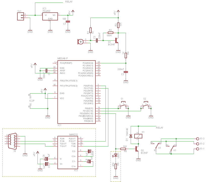
A voltmeter and ammeter using a PIC microcontroller can measure voltage and current simultaneously. This setup employs a PIC16F876A as the data processor for voltage and current measurements. An LCD display (16x2) is utilized to present the measured voltage...
The basic small-range remote controls are Infrared and RF (Radio Frequency). One of the weaknesses of Infrared is that the signal cannot pass through walls. Therefore, to control a garage door, an RF remote control is necessary. The circuit...
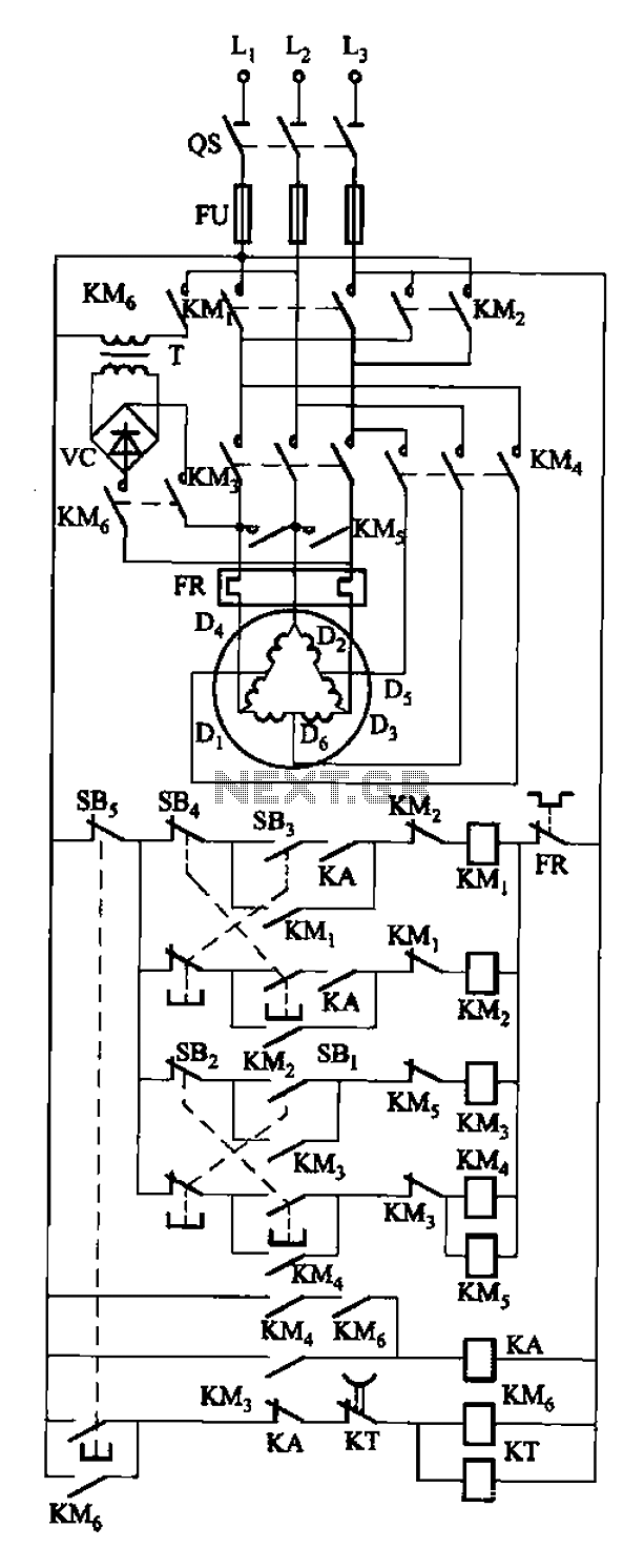
The circuit depicted in Figure 3-108 includes various control buttons: SB3 for the forward button, SI for the reverse button, SBi as the low start button, SB2 for the speed start button, and SBs for the stop button. KMs...
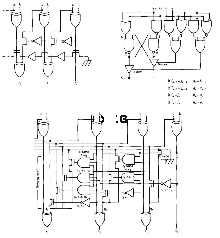
Some circuits that add binary numbers experience time delays due to carry propagation. This issue has been partially addressed by the carry look-ahead adder. However, the complexity of this method typically limits its application to no more than 4...
For those who prefer convenience, it is possible to turn the bedroom light on or off without leaving the bed simply by clapping hands. This concept inspired the design of a clap-activated light control system. Various clap switch projects...