
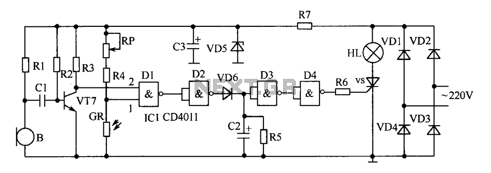
Neon Lamp Flashing Schematic

The described circuit is a simple neon lamp flasher, which utilizes the properties of neon gas to create a visually appealing flashing effect. The operation relies on a charging and discharging cycle facilitated by a resistor-capacitor (RC) network. When the circuit is powered, the capacitor begins to charge through the resistor. The time it takes for the capacitor to charge to the ionization voltage of the neon bulb (approximately 70 volts) is determined by the values of the resistor (R) and the capacitor (C).
Once the ionization voltage is reached, the neon bulb ignites, allowing the stored charge in the capacitor to discharge rapidly through the bulb, producing a flash of light. This discharge continues until the voltage drops below the sustaining voltage (approximately 45 volts), at which point the bulb extinguishes. The capacitor then begins to charge again, repeating the cycle.
The frequency of the flashing can be adjusted by changing the values of R and C. A smaller resistance or capacitance will result in a quicker charge time, thus increasing the flashing frequency, while larger values will decrease the frequency. It is essential to use non-polarized capacitors rated for at least 100 volts to ensure safety and reliability, as the circuit can reach high voltages during operation.
For circuits utilizing multiple stages (more than three bulbs), it is critical that the bulbs are matched in terms of their turn-on voltages to ensure uniform flashing. This matching helps maintain consistent timing and brightness across all bulbs in the sequence. The circuit can be expanded by adding additional RC networks for each subsequent bulb, thus creating a visually dynamic display.In this circuit, one, two or three neon indicator bulbs can be made to flash in sequence at rates determined by the R and C values. In the single stage circuit, using one lamp, the capacitor charges through the resistor until the ionization potential of the neon is reached (about 70 volts) and then discharges quickly through the lamp until the voltage falls below what is needed to sustain the lamp which is approximately 45 volts.
The cycle then repeats at a rate of about 3 Hz for values shown. Smaller R or C values increase frequency, larger values decrease frequency. All capacitors should be the non-polarized variety with a 100 volt or more rating. For more than 3 stages, the lamps may need to be matched for similar turn-on voltages. 🔗 External reference
Related Circuits
It includes a starter for each lamp that heats the filaments (cathodes) at both ends of the lamp before ignition. Once the lamp is lit, the heated filaments are no longer necessary. The heating serves solely as an ignition...
The simple pressure sensor alarm is constructed using a few inexpensive and readily available components. The operation of this circuit is straightforward and self-explanatory. When powered by a 9V compact battery, the active piezo sounder at the output of...
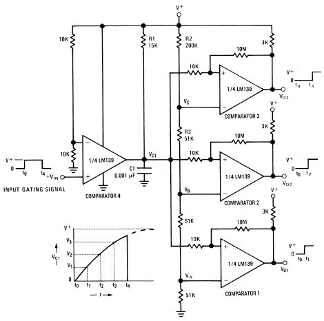
A measure delay generator, also identified similarly to a sequence generator, is a device that provides output signals at specified time intervals from a time reference. It automatically resets when the input signal returns to ground. The schematic illustrates...
The delay-saving lamp circuit functions as a sound and light control delay energy-saving lighting system. It can directly replace a standard light switch without modifying the existing lighting circuits. In bright or daytime conditions, the sound control feature ensures...
This chapter contains circuit diagrams for several power supplies for pulsed solid-state lasers. These include units suitable for driving the popular Hughes ruby and YAG rangefinder laser assemblies, one utilizing the flash from a disposable pocket camera, and a...
This circuit turns off an amplifier or any other device when a low-level audio signal fed to its input is absent for at least 15 minutes. Pressing P1 switches the device on, supplying power to any appliance connected to...