
Neutralizing Amplifier

The schematic for a grid-driven tetrode amplifier with neutralization typically includes several key components: the tetrode tube, input tuning circuit (L1/C1), feedback voltage divider (C2), and the neutralization capacitor (Cneut). The input tuning circuit is crucial for ensuring that the amplifier operates efficiently at the desired frequency. The resonant characteristics of L1 and C1 must be carefully designed to match the operational frequency, as any deviation can lead to instability in the amplifier's performance.
The feedback voltage divider (C2) serves to control the amount of feedback voltage that influences the grid, allowing for fine-tuning of the amplifier's gain. The neutralization capacitor (Cneut) is strategically placed to counteract the unwanted feedback caused by internal capacitances within the tetrode. This capacitor must be adjustable to accommodate variations in frequency and maintain optimal performance across different bands.
In addition to these components, the circuit may incorporate a grid loading resistor to enhance stability. This resistor, when placed close to the tube, helps to mitigate the effects of feedback and can simplify the neutralization process. Proper implementation of these components is essential for achieving a stable and efficient grid-driven tetrode amplifier, capable of delivering high power output with minimal distortion.
Overall, the design and tuning of a grid-driven tetrode amplifier with neutralization require careful consideration of component values, circuit layout, and operational parameters to ensure reliable and efficient performance across the desired frequency range.Grid driven tetrodes like 6146, 807, or 4CX250`s have high power gain. High gain systems require very little feedback to become unstable, so they are generally neutralized. The also often require some form of grid loading resistor to reduce or stabilize gain. The following circuit shows a commonly used tetrode grid-driven amplifier with neutralization: L1/C1 is the normal input tuning coil.
Being resonant on the operating frequency, it inverts phase 180-degrees from end-to-end. C2 is a voltage divider to control the feedback voltage ratio and provide a return path for grid excitation. Cneut is adjusted so its voltage feedback equals the voltage fed through Cgp from plate to control grid inside the tube.
Note that this system depends heavily on L1/C1 being resonant at the operating frequency. This proves the tube is only neutralized at the frequency where C1/L1 is set. It does not stabilize the tube on any frequency except where L1/C1 is resonant. While the feedback adjustment setting of Cneut holds true for multiple bands near the initial adjustment frequency, it only actually neutralizes the tube on the band in use at any moment of time! In a 160-10 meter PA, Cneut generally only works properly over two or three bands. It is usually set near 15 meters so it has the most effect where it is needed most. By the time we get down to 40 meters and lower, feedback voltage through Cgp is generally through such a high reactance that the lack of proper balancing is meaningless.
Additional stability can be added by loading the grid with a broadband termination resistance. This makes neutralization much less critical, and may at times even eliminate the need to neutralize. This resistor would go from the control grid to ground and ideally be added right at the tube. Unless the resistor is an integral part of the bias system, it must be "dc blocked" with a low impedance series capacitance so it does not affect grid bias.
Neutralization generally only affects operation near or at the desired operating frequencies. Neutralization is normally optimized near the upper frequency end of operation, perhaps between 15 and 30 MHz in a 1. 8-30 MHz transmitter or amplifier. Neutralization is sometimes needed because tubes have unwanted internal capacitances. The capacitance between the output element and the input element inside the tube will cause the output circuit to couple back to the input.
If large enough, this regenerative feedback could cause a loss of efficiency. It might cause the output maximum to occur off the plate current dip, reducing efficiency. It might increase IM distortion or in rare severe cases may cause the amplifier to oscillate someplace the operating frequency. (This problem is common with grounded grid amplifiers using 572B`s like the Dentron Clipperton L, or quads of 811A`s, like the Collins 30L1.
Yaesu has this problem is some FL2100`s. ) Neutralization is generally accomplished by adding an external capacitance that is excited exactly 180 degrees out-of-phase with the feedthrough capacitance. One typical adjust procedure is to disable the PA stage by removing anode and screen or filament voltage.
A sensitive RF detector is connected to the transmitter output. Neutralizing a totally cold tube is perfectly fine, because there is very little capacitance shift in a tube with temperature changes. Normal drive is applied, and the neutralizing capacitor is adjusted until feedthrough power is minimum.
The tuning controls are continually peaked for maximum power on the sensitive detector throughout the process. A second less accurate method is to watch the plate current dip in a properly tuned normally operating transmitter.
The neutralization capacitor is adjusted until maximum power output and minimum plate current occur simultaneously as the plate capacitor is tuned. The best method varies with the PA design, but in general the most accurate method is by applying 🔗 External reference
Related Circuits
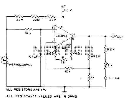
The circuit requires a 15-volt power supply and employs a precision operational amplifier, CA3193 BiMOS, to amplify the generated signal by more than 500 times. Three 22-megohm resistors are utilized to ensure a large-scale output in the event of...
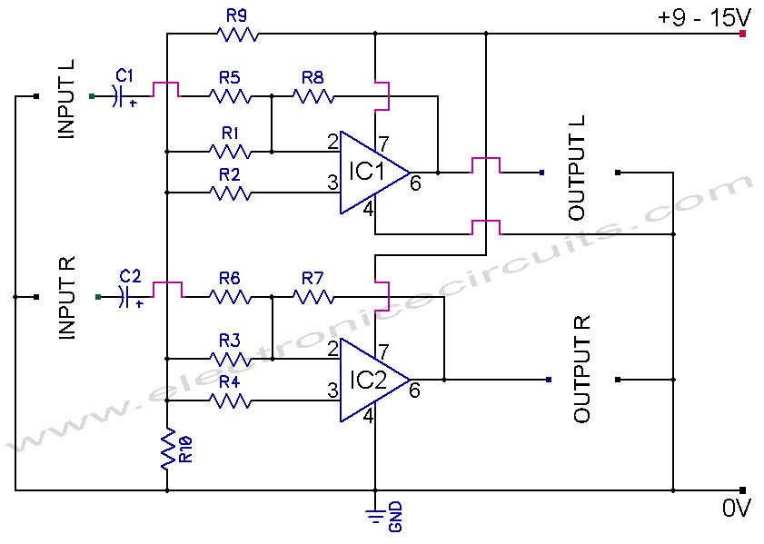
741 Stereo PreAmplifier Circuit Diagram. This preamp circuit provides better than 20dB gain in each channel. PARTS LIST R1 -.. The 741 stereo preamplifier circuit is designed to amplify audio signals with a gain of over 20 dB in each...
This is the schematic of the final design including the tone stack but leaving out the volume, balance, and sonic controls. The right half of the circuit is John Broskie's original White cathode amplifier with a pair of 5687s...
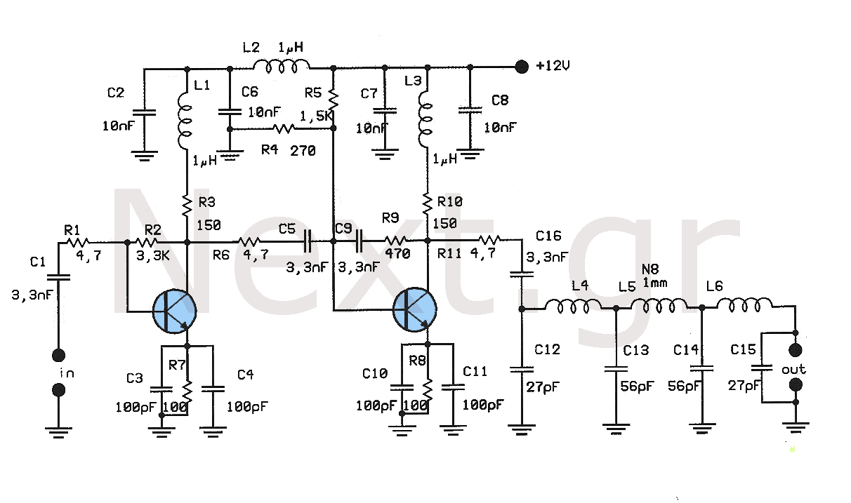
This amplifier is designed to amplify low-level signals from oscillators in the FM band. It lacks frequency regulators with variable capacitors and coils, providing a wide range and moderate power suitable for driving multiple linear amplifiers. The construction utilizes...

A practical amplifier circuit. An electronic amplifier is a device that increases the power of a signal. It accomplishes this by drawing energy from a power supply and adjusting the output to correspond to the input signal shape, albeit...
A voltage between 0.4 and 1.2 V is required on pin 5 to control the gain. In the initial two versions of the circuit, logic ICs and/or counters were utilized along with an operational amplifier and a resistor network...