
Tube Headphone Amplifier II

The 10M resistors (R5 and R13) on the grids of the 12AU7s are not strictly necessary. I included them, however, because I was going to build the amp in stages. I knew that at some point I would want to power it up to measure bias voltages before the volume and tone controls were wired. I needed these resistors to ground the grids and set the proper bias points. I could have just as easily used temporary clip leads to ground the grids when measuring voltages, but adding resistors was not that much extra trouble.
The Fender tone stack is a pure boost tone stack. Unlike the equally well-known Baxandall tone stack, the Fender stack cannot provide bass or treble cut. But, since I never listen with bass or treble cut, the Fender stack offered fewer components and complete capacitor coupling thereby avoiding the use of an additional coupling capacitor from the plate of V1. Like all tone stacks, the Fender tone stack has an insertion loss, in this case approximately 18dB. The "boost" actually comes relative to this loss. In the Fender stack, the mid control is only really active if there is bass and/or treble boost. When the bass/treble controls are off the mid control becomes another volume control.
The parts of the stack form several high-pass filters. The upper part is a high-pass filter through the 250pF capacitor into the treble control whose wiper feeds the next stage. The high-pass bass filter (through the 0.47uF capacitor) sits under the treble control. The high-pass mid filter sits under the bass control. Any signal at the top of the bass or mid controls is fed directly to the treble control's wiper. If the bass control is all the way on, then the low frequencies are passed directly to the wiper. If the bass control is all the way off (zero resistance), then the low frequencies are shorted through the mid control to ground.
The mid control has a higher pass frequency than the bass control. It bleeds off some of the signal that otherwise would pass through the bass section to ground. Because the turnover point is higher than the bass turnover point, and because, when there is treble boost, high frequencies go through the treble section, the mid control has the effect of creating a mid-range notch that in this design is at about 400Hz-1KHz depending on bass/treble settings.
When bass and treble are off, the output sides of the lower two capacitors and the treble control wiper are shorted together and the response is basically flat. The mid control acts simply as a resistance load which, when set to zero, shorts the entire signal to ground. The 27K resistor prevents V1 from seeing a pure AC short to ground. An extremely useful tool for calculating the characteristics of various tone stacks is the Tone Stack Calculator from Duncan's Amp Pages. I used this tool when designing this circuit.
Because the Fender stack introduces an 18dB loss, it was necessary to recover some of this loss with the additional input stage. This stage has a voltage gain of about 5.5 (with a bypass capacitor the gain would have been a little over 10). It does add some distortion to the original design (which has very low distortion), but this was acceptable to experiment with these additional controls. When bass/treble are off and mid is halfway, the total open loop voltage gain is about 7. This is plenty of gain for CD players.
The power supply is a simple solid-state supply, although it is slightly overbuilt. During simulation, it was discovered that if the plate voltage for the input stage were drawn from the B+ (high voltage tap) of the output stage, the circuit would oscillate, even with standard isolation techniques (R-C filtering). The prototype amp hummed slightly. A 5H choke was added to address the hum problem. In the original power supply, the first stage B+ was tapped from the very first filter section. When the choke was installed, all four filter sections were taken from the output of the choke. Both channels share the first two filter stages but have different final filter sections.
The heater supply uses a 12V, 5A low-dropout regulator (Linear Technology LT1084-CT-12). A problem with the amplifier design is the range of heater-to-cathode voltages present. If the heater supply were grounded, the upper tubes would have heater-to-cathode voltages greater than 125VDC, exceeding the 100V specification for the 5687. This was resolved by allowing the heater circuit to DC float but AC grounding it through a capacitor at the mid-point of V1's heater, which is attached to the negative rail of the heater supply.
There are two power switches; one to turn on the heater supply and the other for the B+ supply. The B+ switch is wired to the heater switch as a fail-safe. The design ensures that there are no adverse voltages applied if the B+ comes on before the tubes are conducting, although the heaters are turned on first as a precaution.
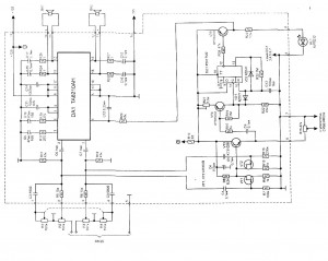
The design compromises due to the spatial control requiring unbypassed cathode resistors. To achieve sufficient gain from the first stage, a fairly high plate resistor was used, resulting in an output impedance of about 8K. The input impedance of the tone stack is approximately 27K at its worst (everything turned off). Although a higher ratio of impedances would be preferable, further modifications to the design were not pursued.This is the schematic of the final design including the tone stack but leaving out the volume, balance, and sonic controls. The right half of the circuit is John Broskie's original White cathode amplifier with a pair of 5687s as output tubes.
This lowers the output impedance to about 27 ohms (gain remains the same) and allows me to set the quiescent current at 17mA per section to preserve tube life while still achieving high current swings with lower distortion. I've increased the size of the output capacitor to get a better lower frequency response at lower load impedances and added good quality audio caps in parallel with the electrolytics.
I also added a fuse after the output capacitors to protect the headphones just in case the electrolytic fails someday. The 10M resistors (R5 and R13) on the grids of the 12AU7s are not strictly necessary. I included them, however, because I was going to build the amp in stages. I knew that at some point I would want to power it up to measure bias voltages before the volume and tone controls were wired. I needed these resistors to ground the grids and set the proper bias points. I could have just as easily used temporary clip leads to ground the grids when measuring voltages, but adding resistors was not that much extra trouble.
The Fender tone stack is a pure boost tone stack. Unlike the equally well-known Baxandall tone stack, the Fender stack cannot provide bass or treble cut. But, since I never listen with bass or treble cut, the Fender stack offered fewer components and complete capacitor coupling thereby avoiding the use of an additional coupling capacitor from the plate of V1.
Like all tone stacks, the Fender tone stack has an insertion loss, in this case approximately 18dB. The "boost" actually comes relative to this loss. In the Fender stack, the mid control is only really active if there is bass and/or treble boost. When the bass/treble controls are off the mid control becomes another volume control. The parts of the stack form several high-pass filters. The upper part is a high-pass filter through the 250pF capacitor into the treble control whose wiper feeds the next stage. The high-pass bass filter (through the 0.47uF capacitor) sits under the treble control. The high-pass mid filter sits under the bass control. Any signal at the top of the bass or mid controls is fed directly to the treble control's wiper. If the bass control is all the way on, then the low frequencies are passed directly to the wiper. If the bass control is all the way off (zero resistance), then the low frequencies are shorted through the mid control to ground.
The mid control has a higher pass frequency than the bass control. It bleeds off some of the signal that otherwise would pass through the bass section to ground. Because the turnover point is higher than the bass turnover point, and because, when there is treble boost, high frequencies go through the treble section, the mid control has the effect of creating a mid-range notch that in this design is at about 400Hz-1KHz depending on bass/treble settings. When bass and treble are off, the output sides of the lower two capacitors and the treble control wiper are shorted together and the response is basically flat.
The mid control acts simply as a resistance load which, when set to zero, shorts the entire signal to ground. The 27K resistor prevents V1 from seeing a pure AC short to ground. An extremely useful tool for calculating the characteristics of various tone stacks is the Tone Stack Calculator from Duncan's Amp Pages.
I used this tool when designing this circuit. Because the Fender stack introduces an 18dB loss, it was necessary to recover some of this loss with the additional input stage. This stage has a voltage gain of about 5.5 (with a bypass capacitor the gain would have been a little over 10).
It does add some distortion to the original design (which has very low distortion), but I was willing to accept this to experiment with these additional controls. When bass/treble are off and mid is halfway the total open loop voltage gain is about 7. This is plenty of gain for CD players. The power supply, Figure 4, is a simple solid-state supply, although it is slightly overbuilt. During simulation I discovered that if the plate voltage for the input stage were drawn from the B+ (high voltage tap) of the output stage the circuit would oscillate, even with standard isolation techniques (R-C filtering).
The prototype amp hummed slightly. I put the 5H choke in to track down the hum problem. In the original power supply, I tapped the first stage B+ from the very first filter section. When I installed the choke I had to take all four filter sections from the output of the choke. Both channels have the first two filter stages in common, but different final filter sections. The heater supply uses a 12V, 5A low-dropout regulator (Linear Technology LT1084-CT-12). One problem with the amplifier design is the range of heater-to-cathode voltages present. If the heater supply were grounded the upper tubes would have heater-to-cathode voltages greater than 125VDC, exceeding 100V specification for the 5687. I solved this problem by borrowing a technique from Bruce Rozenblit (see the OTL design in his book, Audio Reality) where the heater circuit is allowed to DC float, but is AC grounded through a capacitor at the mid-point of V1's heater.
In my case, I attached the capacitor to the negative rail of the heater supply. There are two power switches; one to turn on the heater supply and the other to turn on the B+ supply. The B+ switch is wired to the heater switch as a fail-safe. Studying the circuit I can't see any places where adverse voltages would be applied if the B+ came on before the tubes were conducting.
But, I turn the heaters on first anyway. I had to compromise the design here because the spatial control (described below) requires unbypassed cathode resistors. To get enough gain from the first stage I used a fairly high plate resistor. Together these features give the input stage an output impedance of about 8K. The input impedance of the tone stack is about 27K at its worst (everything turned off). A higher ratio of impedances would be better, but I decided not to mess with the design any further than this.
🔗 External reference
Related Circuits
An essential component of modern multimedia computers is the presence of two active audio speakers, which are typically mounted on or placed next to the monitor. Due to various physical limitations, these small computer speakers are unable to reproduce...
Measure the voltage across the 1k resistor connected to the input stage and Vcc. The DC voltage should be approximately 2 volts, or 2 mA of current flowing through this resistor. For instance, if Vcc is at 24 volts,...
The following circuit illustrates a power supply for an amplifier circuit diagram. Features include ease of construction and adequate electrical response. The power supply circuit for an amplifier is a crucial component that ensures the amplifier operates effectively. It typically...
This audio power amplifier is highly suitable for portable devices or as a headphone amplifier. The circuit design of this audio power amplifier is straightforward. This audio power amplifier circuit is designed to enhance audio signals for portable devices and...

10W audio amplifier with bass boost. High quality, very simple design. No preamplifier required. Circuit diagram: Parts: P1 22K logarithmic potentiometer (dual-gang). This audio amplifier circuit is designed to deliver a power output of 10 watts, making it suitable for...
This circuit is a signal line so that you reinforce with a small speaker can control. The LM 386 is a number of versions available. LM 386N-1 can provide a power of 325 mW, the LM-386N 2500 mW, the...