
Ni-Cd Battery Automatic Charger

The circuit operates by utilizing an LM311 voltage comparator to monitor the charge state of two 350mAh "AAA" Ni-Cd batteries connected in series. The design includes a 20K Ohm multiturn potentiometer that allows for precise adjustment of the reference voltage at the third pin of the LM311. This reference voltage is set to 2.78V, which is critical for determining the charging threshold.
When the combined voltage of the two batteries reaches 2.81V, the output of the LM311 transitions to a high state. This transition is used to control a transistor that interrupts the charging current to the batteries, effectively stopping the charging process to prevent overcharging. The inclusion of a red LED serves as a visual indicator of the charging state; it illuminates when the batteries are being charged and turns off when the charging process has completed.
This circuit design is particularly advantageous for powering portable devices such as digital cameras, wireless headphones, and pocket radios, which typically require two "AAA" batteries. By employing rechargeable Ni-Cd batteries, users can significantly reduce operational costs and contribute to environmental sustainability through reduced battery waste. The automatic charging feature ensures that the batteries are charged efficiently and safely, enhancing the usability and longevity of the devices powered by this setup.The circuit presented in the above schematic has been designed to charge automatically two series 350mAh "AAA" size batteries. Set the 20KOhms multiturn potentiometer to get a 2.78V on the 3rd pin of the LM311 which is a comparator.
So if the net voltage of batteries reaches at 2.81V, the output of the LM311 goes high and then the state of the transistor becomes off, resulting in charging operation stops. When the red LED is lighted, it indicates that the charging is in the progress, and vice versa. To use portable devices such as digital camera, wireless headphone, pocket radio, etc, which they operates with two "AAA" size batteries, using rechargeable Ni-Cd batteries is a conscionable way to reduce cost. 🔗 External reference
Related Circuits
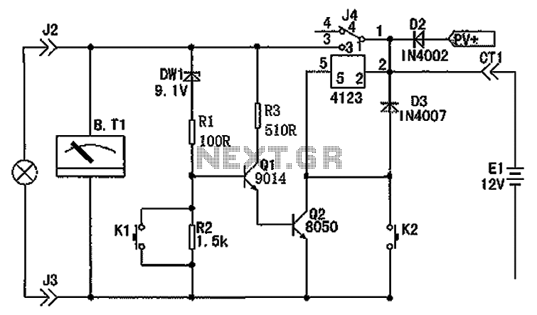
The circuit depicted in the figure consists of a battery, a controller, and various electrical and charging components. It includes a Zener diode (D1) and resistors (R1, R2) for undervoltage detection. The circuit also features transistors (Q1, Q2), resistors...
A new member has joined the forum and is seeking assistance with electronics, particularly from a technical engineering perspective, although they have some experience with circuits and schematics. The individual is likely looking to enhance their understanding of electronic components,...
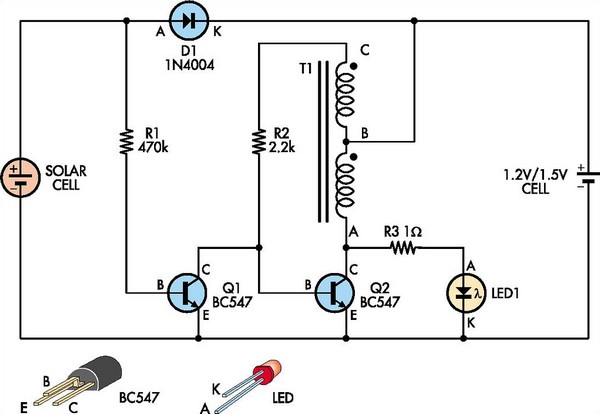
This white LED driver circuit is suitable for garden lighting applications. It automatically activates the LED at night and operates from a single 1.2V NiCad cell, which is recharged by a solar cell during the day. The prototype utilized...
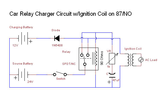
This affordable and simple-to-construct NiCd/NiMH battery charger is designed for the automatic charging of various batteries used in numerous applications. Reliable chargers are typically costly, while inexpensive chargers that come with original equipment often fail to charge cells correctly,...
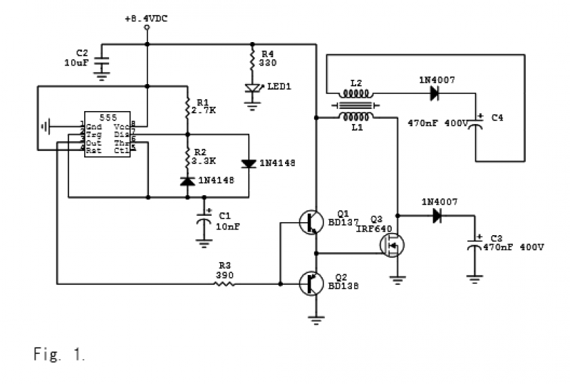
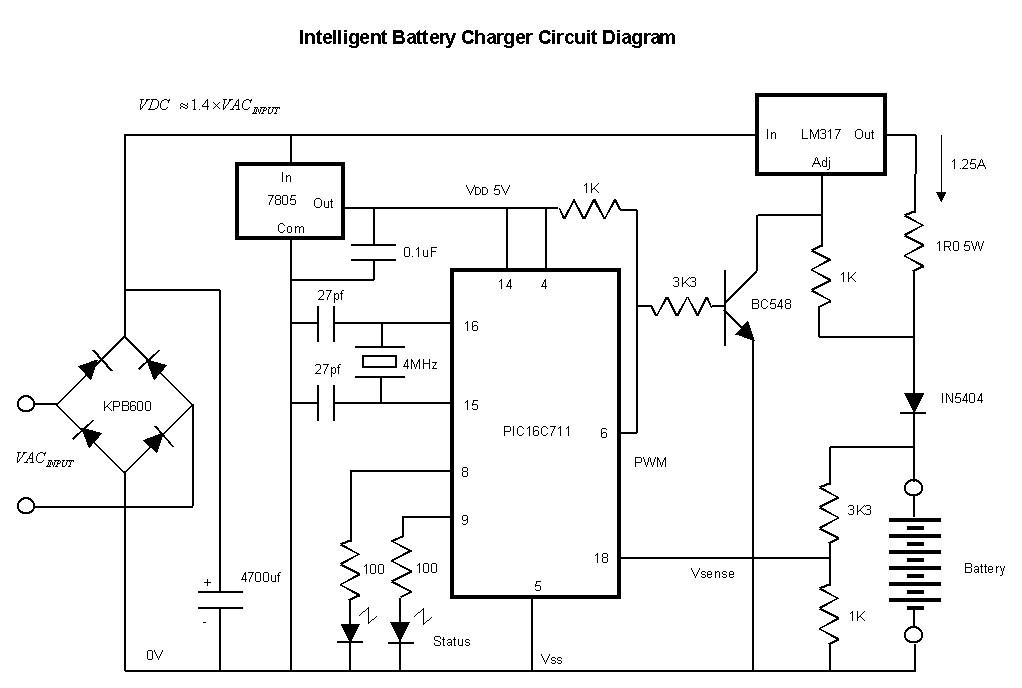
The circuit is depicted in Figures 1-2 and has been successfully tested. It is a charger based on the 555 timer integrated circuit (IC), operating at 8.4 VDC. With resistor values of R1 = 2.7 kΩ, R2 = 3.3...
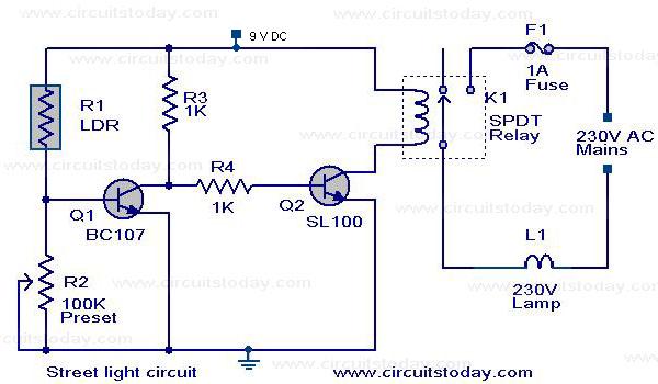
The circuit diagram of an Automatic Street Light Controller Circuit is explained in this post. The Automatic Street Light Controller Circuit is designed to automatically turn on street lights at dusk and turn them off at dawn. This functionality is...