
Automatic Street Light Controller Circuit Using Relays and LDR

The Automatic Street Light Controller Circuit is designed to automatically turn on street lights at dusk and turn them off at dawn. This functionality is achieved using a light-dependent resistor (LDR) as the primary sensor. The LDR detects ambient light levels; when the light falls below a certain threshold, the resistance of the LDR decreases, triggering a transistor that activates the street light.
The circuit typically consists of the following components: an LDR, a resistor for voltage division, a transistor (commonly an NPN type), and a relay to control the high voltage of the street light. The LDR is connected in a voltage divider configuration with a fixed resistor, creating a voltage that varies with light intensity. This voltage is fed into the base of the transistor, which acts as a switch.
When the ambient light level decreases, the voltage across the LDR and resistor combination drops, allowing the transistor to turn on. This, in turn, energizes the relay, closing its contacts and powering the street light. Conversely, when the light levels increase at dawn, the LDR's resistance increases, causing the transistor to turn off and deactivating the relay, thus turning off the street light.
The circuit can also include additional features such as time delay circuits or dimming capabilities to enhance functionality. Overall, the Automatic Street Light Controller Circuit is an efficient solution for managing outdoor lighting, reducing energy consumption, and improving street safety.The circuit diagram of an Automatic Street Light Controller Circuit is explained in this post.. 🔗 External reference
Related Circuits
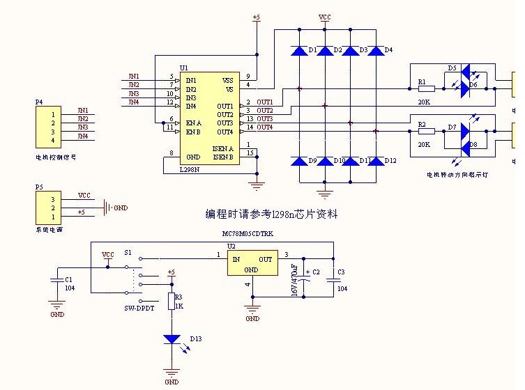
The L298N driver module incorporates the ST L298N chip, commonly utilized to drive two DC motors with voltage ratings between 3V and 30V. It features a 5V output interface that provides power for 5V single-chip circuitry and supports 3.3V...
Figure A illustrates the circuit of a direct-trigger timing light. The trigger voltage is obtained from the car's ignition circuit through a direct connection to a spark plug. Figure B depicts a circuit that employs an inductive pickup. A...
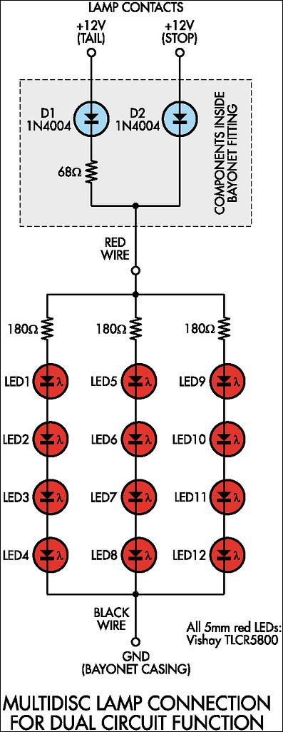
Before proceeding with the implementation, it is important to ensure that the output brightness is adequate for a stop and tail-light application. The light output may vary based on the tail-light lens and reflector assembly, so caution should be...
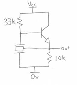
A ceramic resonator can be utilized to construct an oscillator. A single digital inverter can be employed to create a Pierce oscillator. To design a Pierce oscillator using a ceramic resonator and a digital inverter, the following components and configurations...
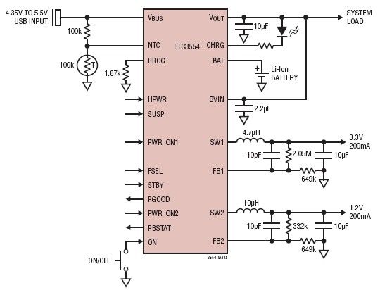
This micropower multifunction power management integrated circuit (PMIC) is designed using the LTC3554, manufactured by Linear Technology Corporation. It serves as a solution for portable Li-Ion Polymer battery-based applications. The LTC3554 integrates a USB-compatible linear PowerPath manager, a standalone...

The adjustable voltage monitor can be used to check whether the voltage in a circuit remains within a given range. If the DC voltage is less than the voltage at pin 5 of U1-B, then LED1 will light. If...