
Light Sensitive Switch with LDR 2N2926

The described light-sensitive switch circuit is designed to detect ambient light levels and activate an output signal when the light intensity falls below a certain threshold. The core components of this circuit are the 2N2926 and AC128 transistors, which serve as the primary switching elements.
The operation of the circuit begins with a light-dependent resistor (LDR) that senses the light level. The LDR is connected in a voltage divider configuration with a fixed resistor. As the ambient light decreases, the resistance of the LDR increases, causing the voltage at the junction of the LDR and the resistor to rise. This voltage is fed into the base of the 2N2926 transistor.
The 2N2926 is configured as a switch. When the voltage at its base exceeds a certain threshold, the transistor turns on, allowing current to flow from the collector to the emitter. This current can be used to activate an alarm or indicator light, signaling that it is dark. The AC128 transistor may be used in conjunction with the 2N2926, possibly in a Darlington pair configuration, to amplify the current and improve the sensitivity of the circuit.
Additional components may include capacitors for noise filtering and diodes for protecting against reverse polarity. The circuit can be powered by a standard DC power supply, with appropriate voltage and current ratings to ensure reliable operation of the transistors.
This circuit can be applied in various applications, such as outdoor lighting systems, security alarms, or automatic night lights, providing a simple yet effective solution for light detection and response.This be circuit warn when be become dark, or Light sensitive switch. By use electronics part the base is important , be the transistor 2N2926 and AC128. For. 🔗 External reference
Related Circuits
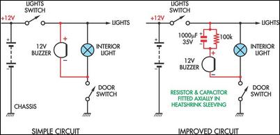
Two headlight reminder circuits are simple to install and operate based on the KISS (Keep It Simple Stupid) principle. The basic circuit consists of a 12V piezo buzzer connected between the lights circuit and a door switch. The buzzer...
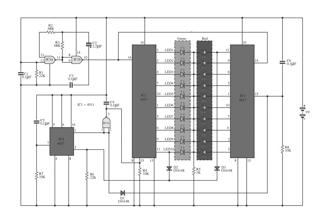
This circuit operates on alternating two colors using a 2-color LED with a built-in 3-pin configuration. It alternates the glow of each LED until the base, switching between two colors. The circuit comprises a NAND gate IC, two 10-counter...
The circuit utilizes relay control. The voice switch operates as follows: upon the first clap, the load (lights) is activated; upon the second clap, the load (lights) is deactivated. This system can be employed to control lighting in residential...

If the ground of the Arduino is disconnected from the negative terminal of the power supply, current flows through the MOSFET, even when the switch is not closed. In an electronic circuit involving an Arduino and a MOSFET, maintaining a...

The circuit for automatic brightness adjustment in a television utilizes a photosensitive resistor and a contrast potentiometer connected to an intermediate stage. The photosensitive resistor varies its resistance based on light intensity, causing changes in the potential at the...

The automatic porch-light control circuit maintains a triac in an active state until a 4020 divider counts a series of 60-Hz power line pulses. This circuit is designed to turn off the light after a specified duration, utilizing pins...