
nimh and nicd battery charger circuit

The circuit employs a 555 timer configured in astable mode to regulate the charging process. The timer generates a pulse-width modulated (PWM) signal that controls a power transistor, which in turn manages the current flowing to the NiCd battery. This PWM technique ensures that the charging current is kept within safe limits, preventing damage to the battery.
Key components include resistors and capacitors that set the frequency and duty cycle of the 555 timer. The output from the timer is connected to the base of a transistor, which acts as a switch. When the PWM signal is high, the transistor allows current to flow to the battery, charging it. When the battery reaches its full charge, the circuit automatically reduces the charging current, thus preventing overcharging.
Additional features may include a diode to prevent reverse current flow from the battery to the charger, ensuring that the battery remains charged and ready for use. An LED indicator can also be integrated into the circuit to provide a visual cue when the battery is charging.
This design is particularly beneficial for applications requiring reliable and maintenance-free battery charging, making it suitable for various electronic devices that utilize NiCd batteries. The simplicity of the circuit allows for easy assembly and troubleshooting, making it an ideal choice for both hobbyists and professionals in the field of electronics.This automatic NiCd charger for 9V NiCd batteries is using 555 timer properties and is very easy to build. Why is an automatic 9 volts NiCd battery charger? Because you can leave the battery for charging as much as you like: it will be always completely charged and ready for use when is needed.
It wont be overcharged and it will not discharge. With the values presented in the circuit diagram, the battery charger NiCd circuit is suitable for 6V and 9V batteries.. 🔗 External reference
Related Circuits
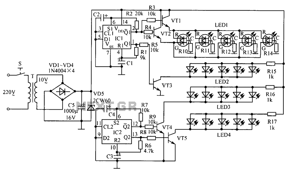
The electronic components designed by conventional electronic bonsai create a sparkling and brilliant atmosphere in the living room, enhancing the joys and pleasures of life. The selection of components includes IC1 to IC4, which consist of two pairs of...
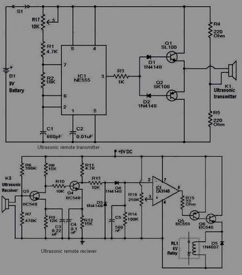
This circuit is straightforward and well-defined. The transmitter operates at 9 volts, while the receiver circuit functions at 5 volts. The transmitter utilizes a 555 timer and two SL100 transistors to perform its function. The receiver incorporates a small...
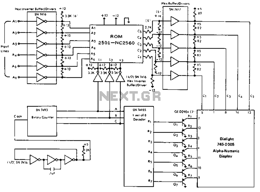
The circuit is capable of driving the company's Dialight 745-0005 monitor, which features a 64-character alphanumeric display. It generates 0-second and 1-second input signals on lines A1 through A6 based on the phase response of the desired characters, utilizing...
Free domains and hosting with up to 1GB of disk space, unlimited transfer, and access to PHP as well as 5 MySQL databases. The maximum size of a single file is not limited. This service offers a robust web hosting...
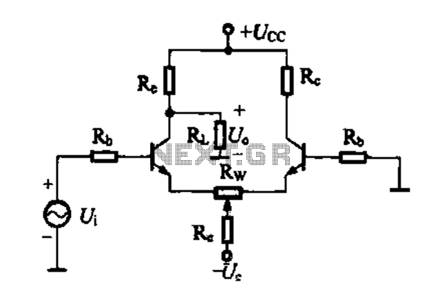
A differential amplifier circuit can be connected in four different ways, allowing for a comparison of their characteristics. The gain of the amplifier is equivalent to that of a single tube, with half the gain providing a high common-mode...
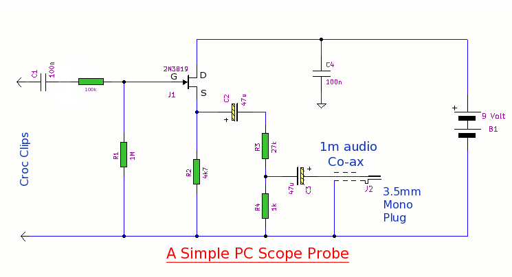
This simple PC scope probe functions as a FET follower, featuring high input impedance and low output impedance to match a microphone or line input socket on a PC or laptop. This design allows for practical examination of waveforms...