
Ultrasonic Remote Control Circuit

The circuit design features a transmitter and receiver system that operates at different voltage levels, specifically 9 volts for the transmitter and 5 volts for the receiver. The transmitter employs a 555 timer integrated circuit, which is widely utilized for generating precise timing pulses and oscillations. This timer is configured in astable mode to produce a square wave output, which is essential for modulating the signal.
To amplify the output from the 555 timer, two SL100 transistors are used in a push-pull configuration. This setup enhances the current driving capability of the transmitter, allowing it to effectively transmit signals over a distance. The choice of SL100 transistors, known for their high gain and frequency response, ensures robust performance and reliability in signal transmission.
On the receiving end, a small relay is implemented to control the desired application or load. The relay acts as an electrically operated switch, which is triggered by the incoming signal from the transmitter. When the relay is activated, it can control higher power devices or circuits, making it versatile for various applications, such as turning on lights, motors, or other electronic devices.
Overall, this circuit design demonstrates a practical application of basic electronic components to achieve wireless communication and control, showcasing the effectiveness of the 555 timer, transistors, and relays in circuit design.This circuit is as shown, simple and clear. The transmitter needs 9 volts and the receiver circuit needs 5 volts. The transmitter uses the 555 timer and two SL100 transistors to make the job. The receiver needs a small relay to control the desired job. 🔗 External reference
Related Circuits
The 27MHz crystal oscillator circuit is illustrated in the figure. Resistors R1, R2, and R3 serve as biasing resistors, while capacitor C6 functions as a bypass capacitor. The voltage division circuit consists of capacitors C1, C3, C4, and C2,...
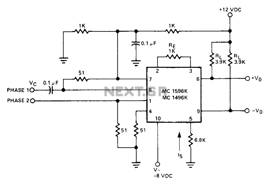
The circuit involves a Signetic balance modem connection utilizing a transistor array as a phase detector. It provides information about the cosine of the phase angle, which corresponds to the frequency of the input signal combined with the integrated...
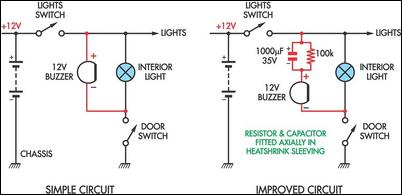
Two headlight reminder circuits are designed for easy installation and operation based on the KISS (Keep It Simple Stupid) principle. The basic circuit consists of a 12V piezo buzzer connected between the lights circuit and a door switch. The...
In the production of LCD projectors, the primary factor threatening the lifespan of the LCD screen is the temperature generated by halogen lamps. The multi-function controller designed by this circuit is highly effective for protecting liquid crystal projectors. The...
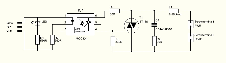
The triac is expected to activate and illuminate the light at nearly 100% brightness; however, it does not turn on at all. If the gate is continuously triggered (i.e., a constant voltage is applied to the gate), the light...
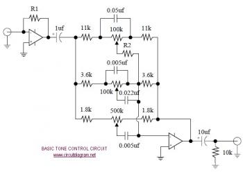
The following diagram illustrates the schematic of an Active Tone Control circuit, commonly referred to as "ACTOR." The ACTOR is an electronic audio circuit designed to enhance loudness by adjusting bass and treble audio signals. It operates using the...