
Nite Rider Lights
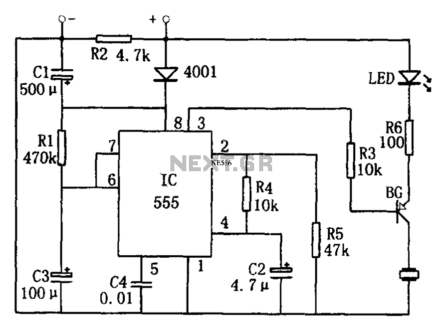
The bicycle lighting circuit employs a NE555 timer IC configured in astable mode to create a flashing LED effect, enhancing visibility and safety during night rides. The circuit is powered by a 9V battery, ensuring sufficient voltage for the operation of multiple LEDs while maintaining low power consumption.
The schematic includes several key components: a NE555 timer, resistors, capacitors, and the LEDs themselves. The NE555 timer is the core of the circuit, generating a pulse-width modulation (PWM) signal that controls the on-off cycling of the LEDs. Resistors are used to set the timing intervals and limit the current flowing through the LEDs, preventing damage and ensuring longevity.
Capacitors are employed to stabilize the voltage levels and smooth out any fluctuations in the power supply, which is crucial for maintaining consistent LED brightness. The arrangement of the LEDs can be customized; they can be connected in series or parallel configurations depending on the desired brightness and aesthetic effect.
This circuit design not only provides an effective lighting solution but also serves as an excellent educational project for those interested in electronics, allowing for practical experience with fundamental components and circuit design principles.Interesting light for your bicycle. Made of LEDs. Very nice! Low power consumption, circuit diagram, electronics project, 9V, NE555.. 🔗 External reference
Related Circuits
This simple circuit drives six LEDs in a "Knightrider scanner mode." Power consumption primarily depends on the type of LEDs used, especially if a 7555 (555 CMOS version) is utilized. The circuit operates by sequentially illuminating the LEDs to create...

The circuit utilizes a Bute CD12V Lee power MOSFET transistor (BU1RF744) that operates in a switching mode, turning on and off repeatedly. The output voltage is influenced by the characteristics of the MOSFET, which is designed for efficient performance....
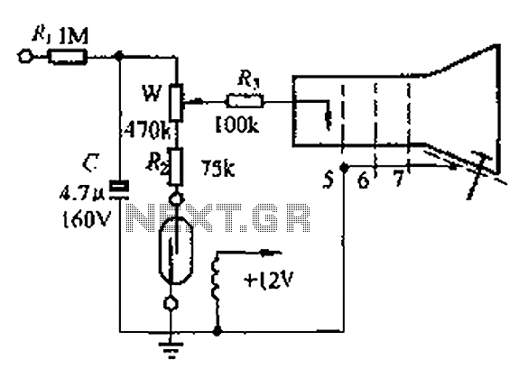
A reed switch is utilized in a TV highlights cancellation circuit. A brightness potentiometer is grounded in series with the reed switch. Under normal operation, the reed contact remains closed, allowing the capacitor C to charge to approximately 160V....
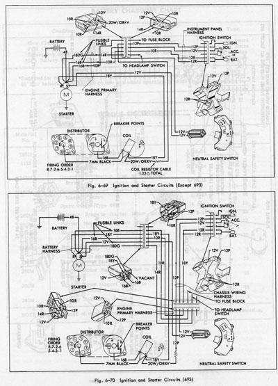
The system operates solely on vacuum. Upon inspection of the vacuum hoses, two brittle hoses were found that ran through the firewall to the headlight switch, where a slight hissing sound was noticeable when the lights were activated. Touching...
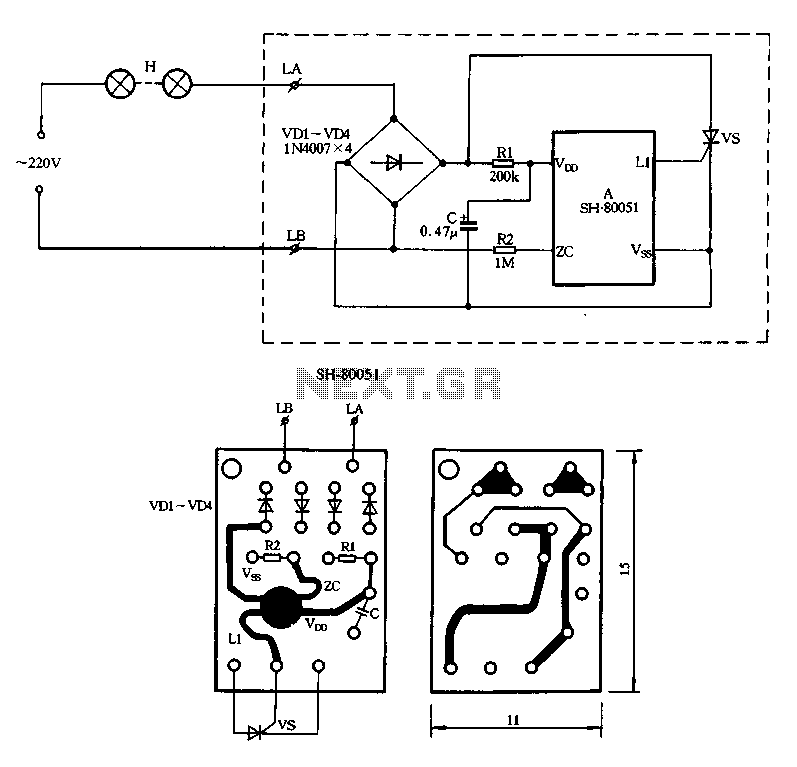
Figure 2-85 illustrates a single-channel SH-80051 flash controller. The SH-80051 chip features four terminals: the positive power supply terminal (VDD), the synchronization input (zc), the negative power supply terminal (VSS), and the drive output (L1). The chip operates with...
The circuit is designed to provide a reminder for lights using a monostable delay configuration. It comprises a monostable delay circuit, a driving circuit, a buzzer, light-emitting diodes (LEDs), and other components. The output signal from the delay circuit,...