
Novice CW Transmitter

The CW transmitter circuit is designed to operate within the amateur radio bands, specifically tailored for novice operators. The circuit's simplicity ensures that it can be constructed with minimal components, making it accessible for beginners. The use of a crystal oscillator provides reliable frequency stability, crucial for effective CW communication. The circuit's design emphasizes safety by isolating high voltages from the operator, while still allowing for effective RF transmission. This transmitter can be a valuable tool for learning Morse code and gaining practical experience in amateur radio operations. The compact chassis design allows for easy integration into various setups, making it suitable for both stationary and portable use. Overall, this CW transmitter circuit remains a practical and educational option for amateur radio enthusiasts looking to engage in CW operation.Even though this CW transmitter circuit was published in 1955 in Popular Electronics, it is still legal for today`s Amateur radio operator. Portions of the 40-meter and 80-meter bands are still reserved exclusively for CW operation. As of 2011 in the 40-meter band 7. 025 - 7. 125 MHz, and for 80-meters 3. 525 - 3. 600 MHz are reserved for CW for Hams holding either Novice (no longer issued) or Technician licenses.
That is different than the frequencies given in the article, so beware if you are tempted to throw one together for old time`s sake. The value for XTAL will need to be changed accordingly. Both bands are a bit lower than shown here, so you might need to tweak the tuning elements a tad as well.
If you are not a designer, you would be better off just finding a newer circuit that is already configured for the new bands. The beginner in ham radio with a novice license should become active as quickly as possible with a low-powered telegraph (CW) transmitter.
Operating this rig as often as he can will give valuable on-the-air experience in handling the code and in correct operating procedure. The best way to learn is by doing. A novice`s first transmitter should be both simple and inexpensive. A good idea is to use the lower frequency bands. There, the new operator usually will find more "rag chewers" and local contacts than on the higher frequency long-distance bands.
In the 80-meter band, novice CW operation is permitted between 3700 and 3750 kc. In the 40-meter band, the novice`s territory is 7175 to 7200 kc. Crystal control must be used. The transmitter shown here was made especially for beginners. While it is low-powered, it will give a good account of itself when operated with a good antenna. It does not take up much room, since it is built on an aluminum radio chassis box (Bender Type 145) 7" long, 5" wide, and 3" high. To reduce expense and to keep hum-producing power equipment off the transmitter chassis, no power supply is built into the transmitter.
This allows the experimenter to use any external unit supplying 250 volts d. c. at 50 to 65 ma. and 6. 3 volts - a. c, or d. c. at 1 ampere. Most experimenters keep a small power supply of this type on hand for general use. Such units also can be bought cheaply in surplus. The necessary a. c. and d. c. voltages often can be drawn from the receiver used with the transmitter. For portable use, a 6-volt storage battery can be used in conjunction with 180 to 225 volts of "B" batteries or a vibrator-type 250-volt supply. The schematic diagram shows the circuit of the transmitter. A 6AQ5 tube (V1) is used in a crystal oscillator circuit. This particular circuit keys quite well. A shunt-fed plate circuit is employed. That is, the output (tank) circuit, consisting of coil L1 and tuning capacitor C7, is isolated from the d.
c. plate voltage of the tube by capacitor C6. This arrangement keeps d. c. voltage off the coil and protects the operator from electric shock. Nevertheless, switch S1 should be thrown to its "off" position before changing coils, since the r. f. voltage may burn the fingers quite painfully just the same. An 8-pin octal tube socket is mounted on the left end of the chassis to hold the crystal. Socket pins 1 and 4 receive the pins of the crystal holder, while other pins of this socket are used as tie points for resistor R1 capacitors C1, and C2, and leads. A 1 1/8" hole is needed for the crystal socket. A 7-pin miniature tube socket for V1, is mounted in a 5/8" -diameter hole near the center. At the right-hand end of the chassis, a 4-pin tube socket is mounted in a 1 1/8" hole to hold the plug-in
🔗 External reference
Related Circuits
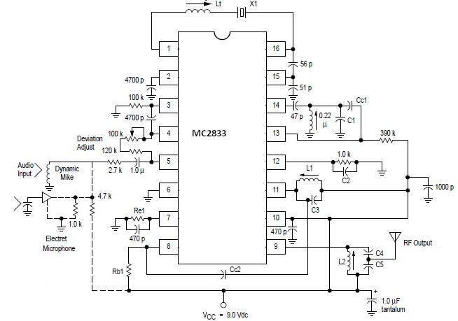
A simple FM transmitter circuit can be designed using the MC2833 integrated circuit, which is intended for cordless telephone and FM communication applications. This circuit includes a microphone amplifier, a voltage-controlled oscillator, and two auxiliary transistors. The final output...

Most consumer electronic devices utilize infrared remote controls for convenient operation. The carrier frequency of these remote controls typically ranges from 36 kHz to 38 kHz. Control codes are transmitted to the device's receiver in a serial format, which...
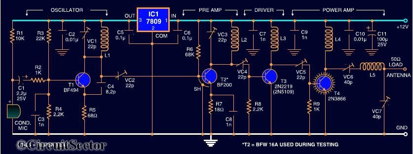
Here is the circuit diagram of a four RF stage FM transmitter. The stages include a very high frequency (VHF) oscillator built around the HF transistor BF494, a pre-amplifier using the BF200 transistor, a driver transistor 2N2219, and a...
This project is straightforward to construct and will transmit high-quality sound within the FM band (88-108 MHz). An important component is that the... This project involves the design and construction of a simple FM transmitter capable of broadcasting audio signals...
Construct this circuit utilizing a Digi-Key Electronics Barrel Crystal (CA-301) with a frequency of 15 MHz to achieve a standard output frequency of 150.00 MHz. For frequency customization, follow the provided instructions. Typically, this circuit is designed to operate...
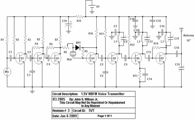
This circuit uses a small microphone to capture the sound and some transistors to generate radio waves that can be picked up by a FM receiver like a car stereo. The first part is the microphone and some resistors...