
NTC protection circuit three-phase asynchronous motors

The semiconductor thermistor serves as a critical component in thermal protection applications, particularly in electrical machinery. Its sensitivity to temperature changes makes it an effective tool for monitoring and controlling the thermal environment of electrical windings, thereby preventing overheating and potential damage. The thermistor's small size allows for easy integration into compact spaces within electrical assemblies, while its reliability ensures consistent performance over time.
In practical applications, the thermistor is positioned in close proximity to the stator windings, where it can accurately measure the temperature of the wire insulation. The use of epoxy cement for securing the thermistor enhances its durability and thermal conductivity, ensuring that temperature readings are representative of the actual winding temperatures.
The choice between NTC and PTC thermistors depends on the specific application requirements. NTC thermistors exhibit a decrease in resistance with an increase in temperature, making them suitable for applications where a drop in resistance indicates a rise in temperature. Conversely, PTC thermistors increase resistance with rising temperature, providing a protective response that can be utilized in over-temperature conditions.
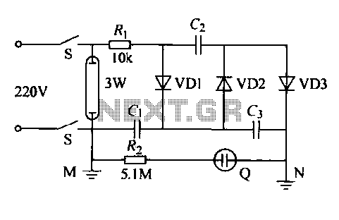
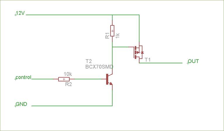
The accompanying circuit diagram, as referenced in Figure 4-1, illustrates the integration of the thermistor within the thermal protection system. The protection circuit is designed to respond to temperature variations by activating a switch circuit, which can be used to disconnect power or trigger alarms when predetermined temperature thresholds are exceeded. The selection of appropriate resistors (R1 and R2) is essential for calibrating the circuit's response characteristics, ensuring that the system operates effectively within the desired thermal limits.
Overall, the semiconductor thermistor is a vital component in maintaining the operational integrity of electrical systems by providing essential thermal monitoring and protection capabilities.Semiconductor thermistor embedded thermal protection element belongs, it is sensitive to temperature, temperature error of 5 . Its reliability , small size (diameter 3. Smm), easy to install, easy to embed winding, use it as a temperature sensing element can effectively reflect the electrical winding temperatures motivation. Thermistor on the three-phase stator windings, close to the wire, with epoxy cement. Thermal resistance has a negative temperature coefficient thermistor (NTC) and positive temperature coefficient thermistor (PTC) of the points.
Circuit shown in Figure 4-1. Wherein Figure 4-1 (b), (c) only one shown protection circuits, the main circuit not shown. They are a switch circuit consisting of a single tube amplifier. Thermistor brother. , R. . , R. , The choice RRC6 type or MF-15 type (lokfl, 20 ), this thermistor in about lkfl 100 when, 110 at about 0.6k, Cl.
Related Circuits
The LA1070 is an automatic gain control integrated circuit designed for use with automotive on-glass antennas. It is produced by Sanyo Semiconductor Corporation. The LA1070 operates by automatically adjusting the gain of the antenna signal to maintain a consistent output...
The following circuit illustrates the use of a 555 integrated circuit (IC) for an infrared (IR) remote control extender circuit. Features include support for 850 nm and 950 nm signal wavelengths, along with the capability to generate control pulses. The...
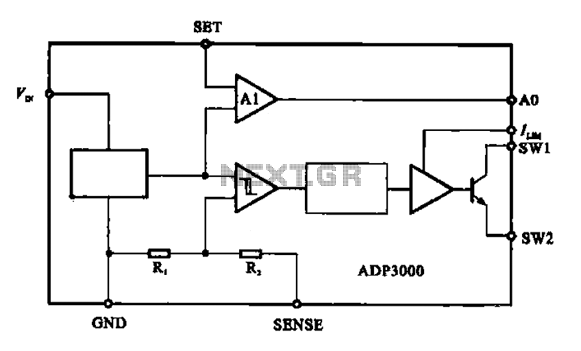
The ADP3000 is an integrated circuit featuring a block diagram that illustrates its internal structure as a high-frequency switching regulator. The ADP3000 integrated circuit is designed to provide efficient power management in various applications, particularly in systems requiring high-frequency switching...
The IED functions as a hotel, restaurant, and family-oriented tool designed for the effective eradication of mosquitoes, as illustrated in Figure 16-12a. It employs a diode voltage doubler rectifier circuit to generate a high voltage. When mosquitoes are attracted...
The schematic is attached. Suggestions for improvements are requested, particularly for adding reverse polarity connection protection. The logic level inputs (5 V) are designed to control two output voltages (12 V) using P-channel MOSFETs. The P-channel MOSFETs are ON...
A simple 3-way crossover, intended for triamping Hi-Fi systems. This is a conventional 12dB / Octave unit, and cannot be expected to have the same performance as a Linkwitz-Riley aligned filter network. It will still be a vast improvement...