
NTSC RGB VIDEO DECODER

The NTSC/RGB decoder circuit employs the TDA3330 integrated circuit, which is specifically designed for processing video signals. The TDA3330 takes a standard 1-V peak-to-peak video input and separates it into individual RGB channels, allowing for high-fidelity color reproduction on RGB monitors. The output from the TDA3330 consists of three separate voltage signals corresponding to the red, green, and blue color components, which can then be fed into the respective inputs of an RGB monitor.
In addition to the RGB outputs, the circuit also provides composite sync output, which is essential for synchronizing the display with the video signal. The LM1881 sync separator, designated as U1, plays a critical role in extracting the sync pulses from the composite video signal. This ensures that the RGB monitor can accurately align the displayed image, preventing issues such as image tearing or misalignment.
The overall design of the circuit is oriented towards compatibility with NTSC video systems, making it an ideal solution for applications that require the integration of RGB monitors in environments where NTSC signals are prevalent. The careful selection of components and the configuration of the TDA3330 and LM1881 ensure reliable operation and high-quality output, making this circuit a valuable addition to video processing systems.An NTSC/RGB decoder is shown here. Using a TDA3330, 1-V input video is broken down into its R, G, B components, and composite synch. U1 is an integrated synch separator (LM1881). This circuit should be useful for interfacing RGB monitors to NTSC video systems. 🔗 External reference
Related Circuits
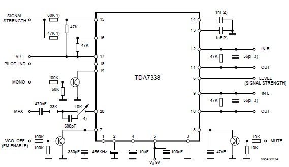
The pilot detector output is configured as an open collector output, necessitating the use of an external pull-up resistor. To set the decoder to "MONO," Pin 19 must be clamped to a voltage lower than 0.8V. The open collector output...
This device and all information contained on this website is intended for educational purposes only. It must be used in accordance with all local, provincial, and federal laws. The end user is responsible for compliance with all legal guidelines;...
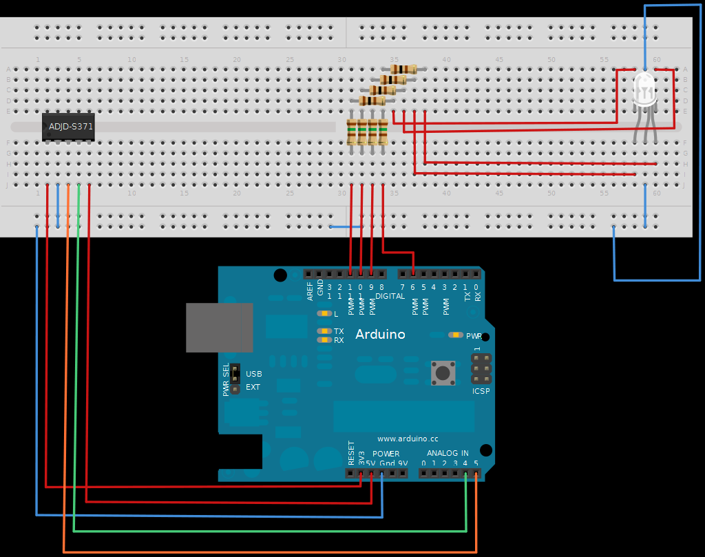
The next board presented is the ADJD-S371 Color Light Sensor Evaluation Board from SparkFun. This board emits light and analyzes the reflected color spectrum. It can be controlled via I2C, while the sleep and xclk pins were not utilized...
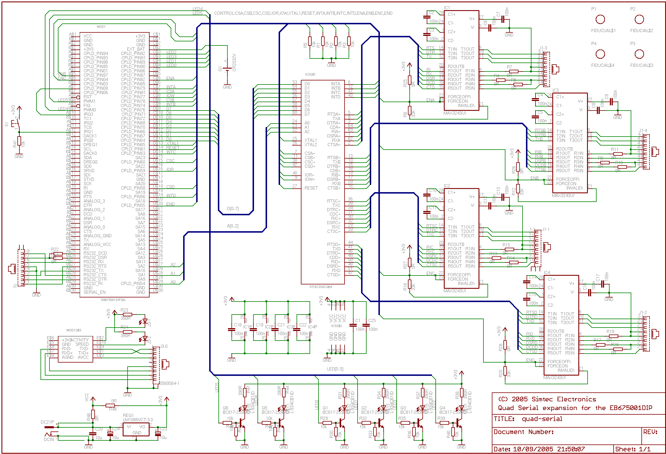
This application note outlines the creation of a basic framebuffer with PAL composite TV output for the EB675001DIP. The design employs a minimal number of additional components to facilitate this display. A user-configurable CPLD is utilized to provide all...
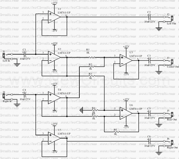
This is a simple surround sound decoder. Left & right outputs of a stereo tape or CD player can be connected to the circuit inputs and 4 outputs of the circuit can be connected to a surround power amplifier...
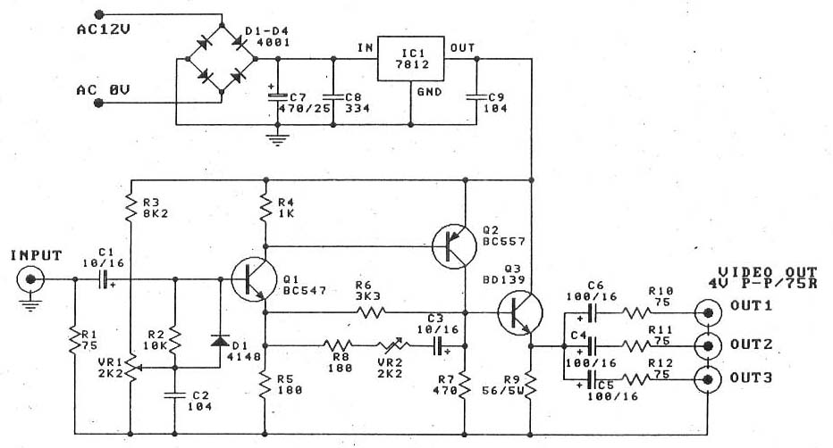
This is a video amplifier circuit or video splitter circuit, designed to strengthen video signals. It compensates for signal loss and is... The video amplifier circuit serves as a crucial component in video signal distribution systems, ensuring that the integrity...