
TDA7338 FM stereo decoder circuit design

The open collector output configuration allows the pilot detector to interface with various voltage levels in a circuit without directly driving the output high. An external pull-up resistor is required to pull the output high when the collector is not connected to ground, thus enabling the detection of the signal state. The value of the pull-up resistor should be selected based on the desired speed of response and the load that the output will drive, typically ranging from 1 kΩ to 10 kΩ.
For the decoder to be set to "MONO," it is crucial that Pin 19 is clamped to a voltage below 0.8V. This can be achieved using a simple clamping circuit, which may consist of a diode and a reference voltage source. The diode will conduct when the voltage at Pin 19 exceeds the threshold, effectively pulling the voltage down to the desired level. It is important to ensure that the clamping mechanism does not interfere with the normal operation of the decoder and that it is capable of handling the expected current without overheating.
In summary, the pilot detector output's open collector design necessitates careful consideration of the external pull-up resistor's value and the implementation of a reliable clamping circuit for proper operation of the decoder in MONO mode.The pilot detector output is designed as an open collector output, therefore an external pull up resistor is needed. To force the decoder to "MONO" Pin 19 has to be clamped to a voltage below 0. 8V. 🔗 External reference
Related Circuits

A simple 16-volt switching power supply circuit can be constructed using the provided diagram, which is based on the MAX668 constant-frequency, pulse-width modulating (PWM), current-mode DC-DC controller. This integrated circuit is designed for a wide range of DC-DC conversion...

The UZZ9000 KMZ41 detection circuit is configured based on the voltage output type and angle. It operates with a +5V power supply. Potentiometers RP1 and RP2 are used for offset voltage adjustment, while potentiometers RP3 and RP4 are utilized...
Many times we needed to use a simple circuit of preamplifier, with few components and facility of made. This circuit uses an opamp, the Motorola, TCA5550, that contains a double amplifier, as outputs for the adjust of volume, balance,...

This circuit consists of a 2 x 22 watt BTL amplifier utilizing the IC TA8210AH. It functions not only as an automobile amplifier but is also suitable for low-frequency sound applications, particularly in high-fidelity audio systems, due to its...
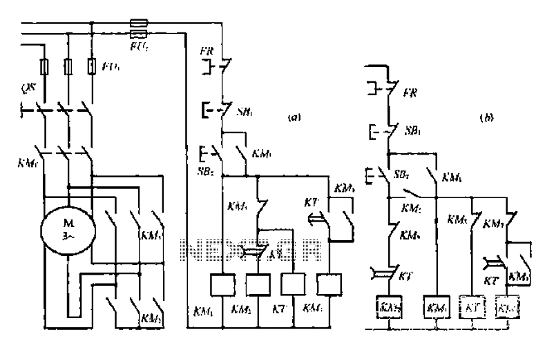
A star-delta switch is utilized for starting circuits, commonly depicted in Figure I-5 (a) of the knife wiring. While this method is effective, it poses security risks. When the motor starts, it can create significant voltage fluctuations that may...
Integrated AF power amplifiers have experienced significant advancements in recent years, offering enhanced power and ease of use. The TDA1519C from Philips features two power amplifiers that provide 11 W per channel in stereo mode or 22 W in...