
O2 Input 0-5v Modification

The described circuit involves careful consideration of voltage levels and signal processing within the Honda ECU's architecture. The use of a wideband O2 sensor in conjunction with the stock ECU necessitates a thorough understanding of the analog input processing stages. The operational amplifier (NJM2904) serves to amplify the signal, but its limitations require strategic modifications to achieve optimal performance. The multiplexer (MC14051) efficiently routes the selected input to the ADC while maintaining signal integrity. The ADC, typically configured to convert voltages from 0 to 5V, is crucial for translating analog signals into a digital format that the ECU can utilize for engine management purposes.
In practical applications, ensuring compatibility between the wideband output and the ECU input is paramount. Modifications to the circuitry, such as bypassing the op-amp, demonstrate the necessity for iterative testing and validation of circuit behavior. The implementation of a feedback loop or additional filtering may further enhance the stability and accuracy of readings, particularly in dynamic operating conditions. Overall, this circuit exemplifies the intersection of analog signal processing and digital control systems in automotive applications, highlighting the importance of careful design and adaptation to meet specific performance criteria.Software such as that available on PGM-Fi. org and from Hondata make use of the Honda ECU`s oxygen sensor input to allow real time display and data logging of wideband oxygen sensors. This involves feeding the analogue output of the wideband sensor`s controller in through the stock (narrowband) O2 input.
The known relationship of voltage to AFR is then entered into the software package you are using to allow it to log a real world value. The wideband set-up I purchased a while ago from Innovate Motorsports features two independent programmable outputs with a maximum 5v range of operation. This allows you to set each output to supply a voltage of 0-5v in almost any linear relationship to AFR in the controller`s operating range, typically 10:1-20:1 AFR.
The most logical way to configure the unit would be 0v for 10:1 and 5v for 20:1, but there is a limitation with the stock ECU that prevents us from doing this. The stock Honda O2 sensor input will only read to a maximum of around 3. 8v, this does not present any problem when the stock narrowband O2 sensor is used as hovers about the 1v area in operation.
While you could just configure your WB controller to output from 0-3. 8v from 10:1 to 20:1 AFR, it would be a lot more accurate if you could read to 5 volts. Another problem is that many WB O2 controllers (like the AEM, TechEdge etc) do not allow you to alter the wideband signal output - this means any AFR above the 3. 8v threshold will not be read! Various people in the past have used op-amps to rescale the 0-5v output of these wideband controllers to meet the restraints of the ECU, and while it gets the job done it would be nice to have everything done properly.
To get around this limitation I started tracing the input stage to for the O2 sensor input, as most other analogue inputs on the ECU will read to 5 volts. A block diagram of the O2 sensor input stage of the USDM P28 ECU is shown below - I have checked many other OBD-1 ECU`s and they all operate in a similar fashion.
Three main components are shown, an Op-Amp (NJM2904), Multiplexer (Mux) (MC14051) and the ubiquitous 66207, or more correctly one of the 66207`s analogue to digital converter (ADC) inputs. The diagram is simplified and only shows what we are concerned with. The analogue Mux is best thought of as a multi-pole switch with many inputs and one output (which is fed to the ADC) as the switching action does not affect the signal on its way through.
The Mux has pins that allow the ECU`s processor to select which input it wants to read at any one time, and the ECU cycles through all of the inputs very fast - this allows it to take a snapshot of many different inputs, with only one ADC input. This saves money, as what would be one input channel now becomes many. The time the CPU takes to scan all of these inputs and get back to the start does not worry us here, as the signals it is reading do not change fast enough to be a concern - the CPU "switches" between inputs very fast compared to the speed of change of the input signal, so for all intents and purposes its as good as a direct ADC input.
The ADC is converts the analogue voltage of 0-5v in this case into a numerical representation of that voltage that the CPU can understand, and store in its memory. Notice I say 0-5v - this is because the ADC is actually configured to read from 0-5v although the O2 input is processed so to limit the maximum voltage the ADC sees to 3.
8v. The most simple way to find out what the problem is would be to apply 5v onto the O2 input, and watch for it becoming altered along the route. That done it was discovered that the Op-Amp stage was limiting the voltage seen by the ECU. This being the case I bypassed the op-amp by lifting a resistor and applied 5v directly to the Mux, and without much surprise we now see the ECU reading to 5v (or as close as it will ever get) - great stuff!
That done, another problem reared its head. I 🔗 External reference
Related Circuits

Circuit with electronic symmetrical input, with possibility of regulation of the gain from the pontesometer RV1 and the level of signal with the RV2. The quality of pontesometer RV1 (as other material), should be very good, in order to...
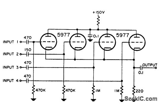
This circuit is utilized for combining four distinct positive-polarity marker pulses in a radar system. The reference for this information is the "Handbook Preferred Circuits Navy Aeronautical Electronic Equipment," Volume 1, Electron Tube Circuits, published in 1963, page N4-1. The...
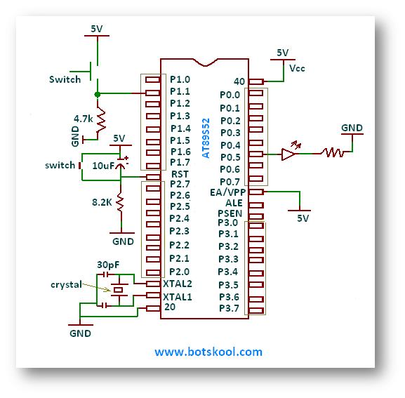
This tutorial continues the discussion on 8051 Assembly Programming by teaching input and output instructions for 8051 microcontrollers using assembly language. The microcontroller comprises a total of forty pins, most of which serve multiple functions. The primary function is...
Upgrading to a 3-prong AC cord is a common modification, as is the replacement of filter capacitors. Switching coupling capacitors to brands like Orange Drops or other boutique options is also popular, often enhancing the appeal in online auctions....
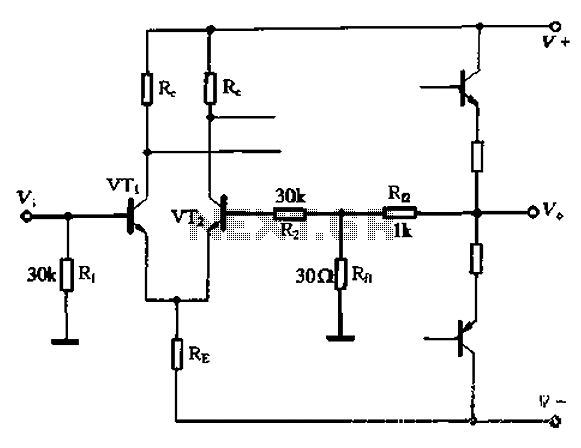
The circuit utilizes the configuration illustrated in Figure 1-36, with the feedback circuit and bias circuit implemented separately. The feedback resistor, Rfl, is approximately 30 ohms. To maintain the desired amplification, the resistor R queue is set to 1...
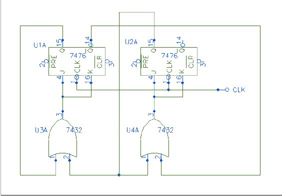
Q1 and Q2 form a table. On the left side, list the four possible states of Q1 and Q2; on the right side, write the values that Q1 and Q2 will assume after the next clock pulse. The table...