
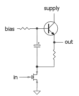
A feedback circuit and the differential input stage bias circuit is provided separately

The circuit configuration described is typical in amplifier designs where feedback and biasing are critical for maintaining performance and stability. The feedback resistor, Rfl, plays a significant role in determining the overall gain of the amplifier. By setting Rfl to approximately 30 ohms, the circuit can achieve a specific level of feedback that stabilizes the gain and reduces distortion.
The resistor R queue, placed between the base and the right transistor's emitter, is crucial for controlling the input impedance and ensuring that the transistor operates within its optimal range. The choice of 1 kilo-ohm for R queue is a standard practice to balance the input characteristics of the amplifier.
In addition, the matching of the left and right transistor base resistances via Rtz ensures that both transistors operate symmetrically, which is essential for minimizing discrepancies in amplification and maintaining linearity across the circuit. The careful selection of R2 to equal R1 further reinforces this symmetry, allowing for consistent biasing across both sides of the circuit. This design consideration helps to prevent input resistance reduction, which could adversely affect the circuit's performance.
Overall, the described circuit demonstrates a thoughtful approach to amplifier design, focusing on feedback, biasing, and input resistance to achieve reliable and efficient operation. Circuit using the form shown in Figure 1-36, the feedback circuit and the bias circuit separately, Rfl take about 30fl. To ensure put magnification, R queue take lkflo between the base and the right pipe string Rtz same people and left tube base resistance R value resistor R2, so that R2 Rl F30kfIO such bias can be consistent on both sides, and input resistance is not reduced.
Related Circuits
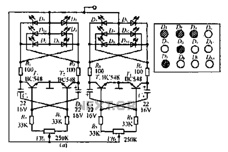
A circuit involving oscillations is composed of a Houle Wang oscillator that utilizes a transistor configuration with components labeled Ti, n, and n, along with a composition of Q constants for the cycle. The waveform can be modified by...
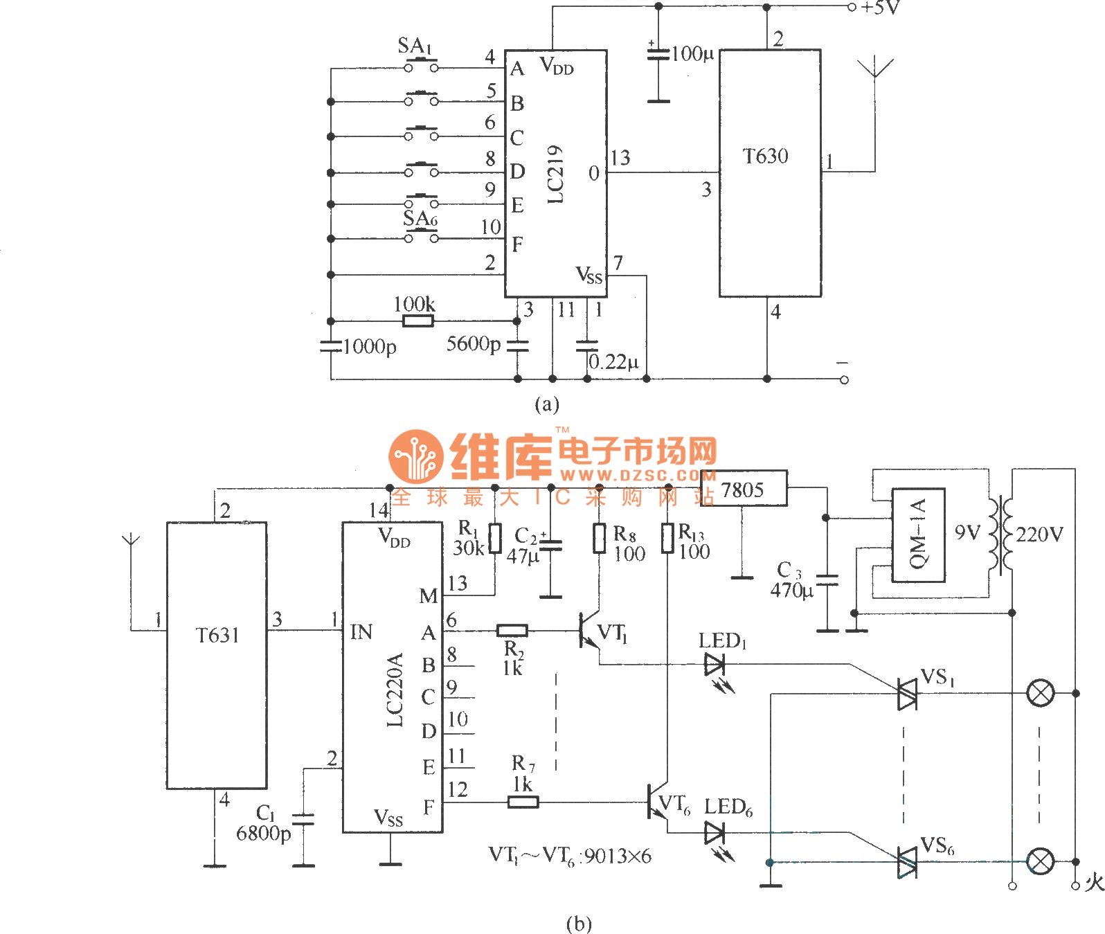
The circuit utilizes the long-wave wireless transceiver T630/T631 to manage a 6-channel load. It is characterized by low power consumption, high resistance to interference, and a simple structure. The circuit design incorporates the T630/T631 transceiver, which operates in the long-wave...
A newcomer to the forum is seeking assistance with DIY electronic circuits and lacks a formal background in electrical engineering. The inquiry indicates a desire to learn and engage with the community on topics related to DIY electronic circuits. For...
This amplifier is designed to be self-contained within a compact loudspeaker enclosure. It can be powered by devices such as Walkmans, Mini Discs, iPods, CD players, computers, and other devices equipped with line or headphone outputs. Typically, two units...
The audio source will be a line-level audio signal ranging from -2V to +2V AC, which will be passed through a 220µF coupling capacitor followed by a two-pole low-pass filter (RC). The signal will be processed by an Analog-to-Digital...
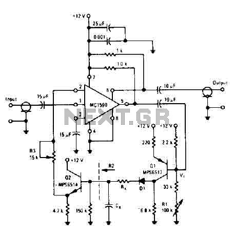
The amplifier drives the base of a common emitter PNP MPS6517, operating with a voltage gain of approximately 20. The RL control adjusts the quiescent point of transistor Q, allowing varying amounts of input signal to exceed the reference...