
Old Valve Amplifier

The presented schematic illustrates a valve or tube audio power amplifier, which utilizes vacuum tubes to amplify audio signals. This type of amplifier is known for its warm sound characteristics and is often favored by audiophiles and musicians for its unique tonal qualities. The amplifier typically consists of several stages, including a preamplifier stage, phase splitter, and output stage, each responsible for progressively increasing the audio signal's power.
In the preamplifier stage, low-level audio signals are applied to the input of the first vacuum tube, where they are amplified to a higher voltage level. This stage may incorporate components such as resistors, capacitors, and transformers to shape the frequency response and manage signal integrity. Following this, the phase splitter stage ensures that the signal is split into two equal but opposite phases, which is crucial for driving the push-pull output stage effectively.
The output stage, often featuring a pair of output tubes, amplifies the signal to a level suitable for driving loudspeakers. This stage may include output transformers to match the impedance of the tubes to the speakers, ensuring optimal power transfer and minimal distortion.
Additionally, the schematic includes a type 390 Rectron B eliminator, which serves as a power supply component. This eliminator converts AC voltage from the mains supply into the DC voltage necessary for the operation of the vacuum tubes. It typically consists of a rectifier, filter capacitors, and voltage regulation components to provide stable and clean power to the amplifier circuit.
Overall, the combination of the valve audio power amplifier and the Rectron B eliminator in the schematic represents a classic approach to audio amplification, emphasizing both the aesthetic and functional aspects of tube technology in sound reproduction.The schematic shows a valve / tube audio power amplifier and a type 390 Rectron B eliminator. 🔗 External reference
Related Circuits
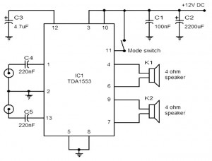
The provided schematic represents a car stereo amplifier circuit that can be utilized in cars or other vehicles. The circuit is based on the TDA1553, which is a Class-B audio amplifier. This circuit is straightforward, consisting solely of the...
The TDA8932B/33(B) can operate with a symmetrical power supply. In this configuration, three half supply voltage buffers are disabled when powered from a symmetrical source. The TDA8932B/33(B) is a high-efficiency Class D audio amplifier designed for various audio applications. Operating...
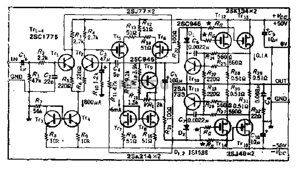
The circuit consists of three identical basic stages, with the second stage featuring a differential output from the power MOSFET, 2SJ77. A current mirror circuit utilizing 2SK214 is implemented. The operating current is 6mA; however, due to the power...
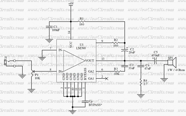
This circuit is a mono audio amplifier that will boost low frequencies as you see at the frequency response. The circuit is suitable for driving a subwoofer speaker for example. The output power of the circuit is about 1...
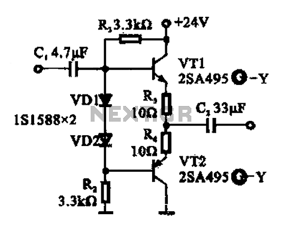
A buffer amplifier is utilized as a transistor emitter follower buffer amplifier for applications that necessitate a high input impedance. The circuit employs a complementary push-pull configuration. The signal input is connected to the base of transistor VT1, which...
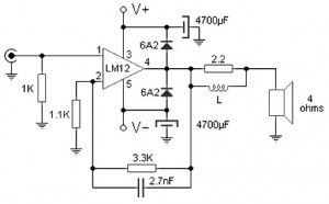
The 100W audio power amplifier is powered by the integrated circuit LM12CLK, which is an operational power amplifier. The 100W audio power amplifier utilizing the LM12CLK integrated circuit is designed to deliver high-quality audio output with significant power handling capabilities....