
Buffer amplifier

The buffer amplifier described functions primarily as an impedance matching device, allowing signals from high impedance sources to drive lower impedance loads without signal degradation. The configuration of the amplifier as an emitter follower ensures that the output voltage closely follows the input voltage while providing a significant increase in current drive capability.
In this circuit, the transistor VT1 acts as the main amplifying element. The high input impedance is achieved through the use of a resistor divider network that biases the base of VT1, allowing minimal loading on the input signal source. The inclusion of the two forward-biased diodes serves to stabilize the base voltage against fluctuations, enhancing the performance of the amplifier under varying conditions.
The complementary push-pull arrangement typically involves a second transistor, which can be configured to handle the negative half of the signal cycle, thereby improving linearity and reducing distortion. This configuration allows the circuit to efficiently drive loads while maintaining signal integrity.
The output stage of the buffer amplifier, characterized by its dual emitter output, results in low output impedance. This is advantageous for driving capacitive loads or long cable runs, as it minimizes signal loss and ensures that the load receives a faithful representation of the input signal. The overall design is particularly suited for applications in audio amplification, sensor interfacing, and other scenarios where signal fidelity and impedance matching are critical. Buffer amplifier Shown in use as a transistor emitter follower buffer amplifier for applications that require high input impedance of the amplifier. Complementary push-pull cir cuit the circuit configuration, the signal input from the base of VT1, two transistor base bias resistor divider type, the base of the transistor both indirect two forward biased diodes, to maintain the base voltage static stability, since the circuit dual emitter output circuit, because the output impedance and low output has strong ability.
Related Circuits
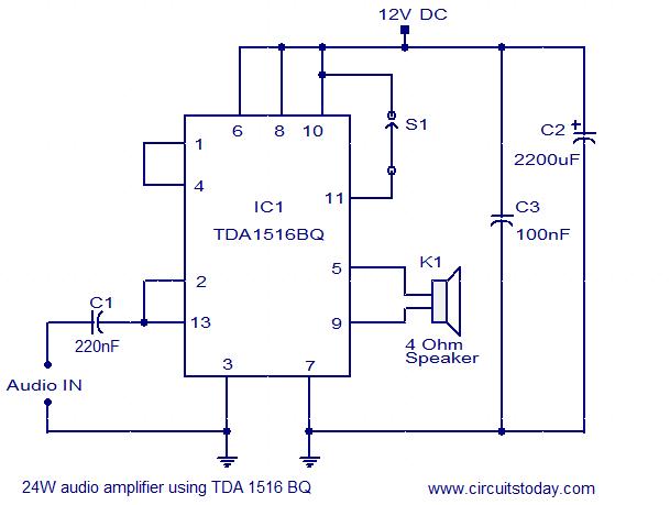
The circuit diagram illustrates a simple 24W mono amplifier utilizing the TDA1516 integrated circuit. The TDA1516 is a Class B power amplifier packaged in a 13-pin SIL configuration. This integrated circuit includes several beneficial features, including short circuit protection,...
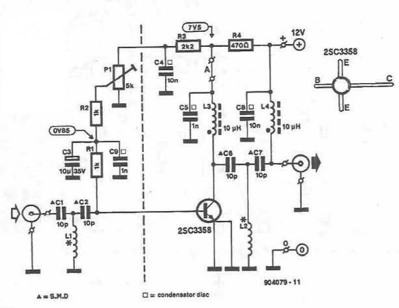
This UHF amplifier circuit project is beneficial for enhancing weak TV signals. The amplifier provides a gain of 10-15 dB within a frequency range of 400 to 850 MHz. To ensure optimal performance and reliability, the PCB tracks should...
Explore the power amplifier integrated circuit from National Semiconductor, the LM4780. What is noteworthy about this component is its very low harmonic distortion. Typically, manufacturers specify the maximum power of their products with a harmonic content of around 10%....
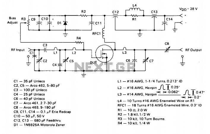
This amplifier operates from a 28 V DC supply. It has a typical gain of 12 dB and can withstand operation into a 30:1 VSWR load at any phase angle without sustaining damage. This indicates that with the input...
Even if the circuit is simple, it complies with all conditions regarding distortion and frequency response. The input resistance is 250K ohms, and it can drive loads ranging from 100 ohms to 2K ohms. The described circuit is a fundamental...
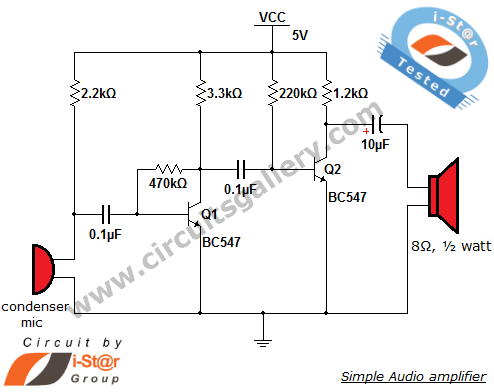
This circuit diagram is a simple and effective design for amplifying weak signals from a capacitive condenser microphone. It is suitable for sound sensing applications and various automatic robotic sensors. While a more complex audio amplifier circuit using the...