
One battery fast charge circuit

The described charging circuit employs a sophisticated method to optimize battery performance by utilizing a rapid charge and discharge cycle. The system is designed to monitor the battery voltage continuously and respond accordingly to prevent excessive polarization, which can lead to reduced battery lifespan and efficiency. The integration of a potentiometer allows for fine-tuning of the discharge time interval, adapting the charging process to the specific state of the battery.
In practical terms, this circuit can be implemented using a microcontroller or a dedicated battery management IC that can handle the necessary voltage and current levels. The circuit would typically include components such as a voltage sensor to detect the battery voltage, a current sensor to monitor the charging and discharging currents, and a relay or MOSFET to control the charging path.
The charging algorithm can be programmed to initiate charging at a high current until the voltage reaches the polarization point, at which point the system would switch to a discharge mode to reduce voltage and alleviate polarization. Following this, the system would resume charging at a high current, ensuring that the battery is charged efficiently without overheating.
Thermal management is also an essential aspect of this design, as rapid charging can generate heat. Adequate heat sinking or cooling mechanisms should be incorporated to maintain optimal operating temperatures.
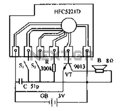
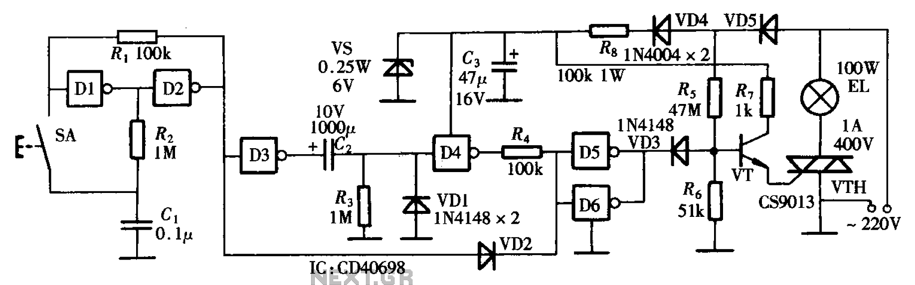
Overall, this advanced charging circuit not only improves charging efficiency and speed but also extends the life of the battery, making it suitable for applications such as electric vehicles and high-capacity battery systems.Fast and efficient charging is higher than conventional charging ten times to several times the current charge. When the battery voltage rises to a predetermined value when (va porization point), polarization within the cell is more serious, it should stop charging. And then let the battery instantaneous large current discharge, the battery voltage drops rapidly, quickly disappeared polarization, and then use a large current continues to charge, so the anti- complex circulation. When such a charging method, temperature is not high, charging speed, efficiency up to 90%, can improve the storage life of the pool.
Fast-charge, original charging time can be shortened to about 20h 1-2h, and can save energy by 20% - 25%. Circuit is shown. It can be used as 12V car battery. Adjustment potentiometer RPi, change the discharge time interval. Pay special attention to the charging and discharging time interval to be transferred to the battery in the electrochemical reaction rate to adapt.
When the battery voltage is low, the electrochemical reaction quickly, so a shorter time interval some; while the battery close enough, the interval should be longer.
Related Circuits
The circuit utilizes a thermistor and three sections of a LM3900 quad operational amplifier (op amp) integrated circuit. When the temperature decreases to 36°F, an LED indicator flashes approximately once per second. As the temperature continues to drop to...
Do not drink and drive. Wishing you a safe journey home. Language Integrated Circuits. Language Integrated Circuits (LICs) are specialized electronic components designed to facilitate the processing of language-based data within various applications. These circuits integrate multiple functions, such as...
In this doorphone circuit, an 8 ohm speaker is used both as a microphone and also an output device. The BC109C stage amplifies in common base mode, giving good voltage gain, whilst providing a low impedance input to match...
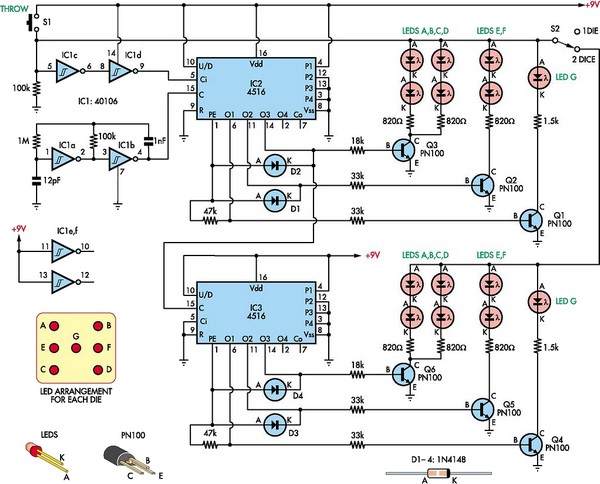
This circuit utilizes two 4516 integrated circuits (ICs) to simulate a game involving two dice. A switch is included to select whether one or two dice will be activated with each press. A 9-volt battery is sufficient for power...
The bedside door fixture delay circuit features a straightforward design and offers cost-effectiveness. It is constructed using a hex inverter CD4069. The bedside door fixture delay circuit employs the hex inverter CD4069, which is a versatile integrated circuit (IC) commonly...
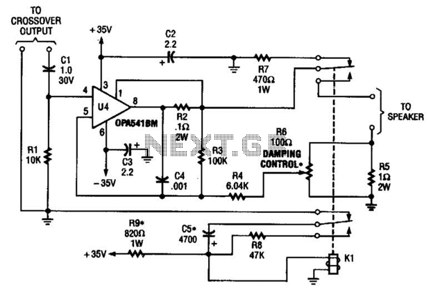
Designed to power a low-frequency subwoofer speaker system, the amplifier can deliver up to 100 W into an 8-ohm load. The OPA541BM operational amplifier, produced by Burr-Brown Corporation, necessitates heatsinking for optimal performance. Additionally, the design incorporates a damping...