
Doorphone Intercom schematic

The doorphone circuit operates by utilizing an 8-ohm speaker for dual functionality, serving as both a microphone and an audio output device. The circuit begins with the BC109C transistor, configured in a common base mode, which is advantageous for providing a high voltage gain while ensuring a low impedance input. This configuration is essential as it effectively matches the impedance of the 8-ohm speaker, facilitating efficient signal transfer.
The self DC biasing technique employed in the BC109C stage is designed to accommodate variations in the transistor's current gain, ensuring stable operation across different conditions. This feature is critical for maintaining consistent performance in various environmental scenarios, which may affect the transistor's characteristics.
Following the initial amplification stage, an LM386 power amplifier is integrated into the circuit in a non-inverting configuration. This component is pivotal for further boosting the voltage gain, enabling the circuit to drive the 8-ohm speaker effectively. The LM386 is known for its low power consumption and ability to deliver sufficient output power, making it suitable for battery-operated devices like doorphones.
Volume control is achieved through a 10k potentiometer, allowing users to adjust the audio output level according to their preferences. Additionally, a 5k preset resistor is included in the design to provide further adjustments to the overall gain of the circuit, facilitating fine-tuning of the audio performance.
The circuit also incorporates a double pole double throw (DPDT) switch, which serves to select between different operational modes or to engage/disengage specific components of the circuit as needed. This flexibility enhances the functionality of the doorphone, allowing it to adapt to various usage scenarios.
Overall, the design of this doorphone circuit emphasizes efficient audio processing and user control, ensuring a reliable communication solution.In this doorphone circuit,an 8 ohm speaker is used both as a microphone and also an output device. The BC109C stage amplifies in common base mode, giving good voltage gain , whilst providing a low impedance input to match the speaker. Self DC bias is used allowing for variations in transistor current gain. An LM386 is used in non-inverting mode as a power amplifier to boost voltage gain and drive the 8 ohm speaker. The 10k potentiometer acts as the volume control, and overall gain may be adjusted using the 5k preset.
The double pole double throw switch, rev 🔗 External reference
Related Circuits
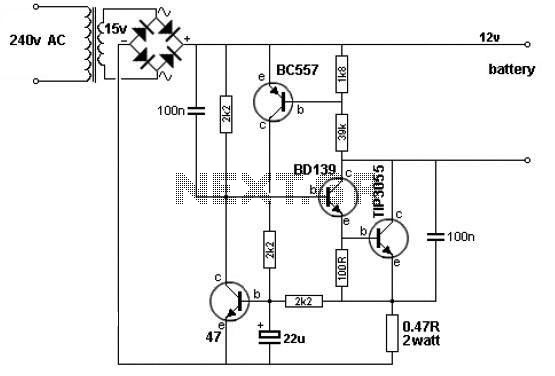
A simple 12V battery charger circuit can be designed using a TIP3055 power transistor to limit the current to the battery. The circuit turns off when the battery voltage reaches approximately 14V or if the current exceeds 2A. This...
Switching regulator subsystems are designed for use as DC to DC converters. The 3V to 40V DC converter circuit utilizes switching regulators, which are increasingly favored over linear regulators due to the demand for higher conversion efficiency in modern...
The intercom schematic provides a reliable communication line and is straightforward to construct. The circuit consists of an amplifier, two switches, and two loudspeakers. If additional stations (speakers) are desired, more switches can be incorporated into the circuit. The...
There are at least three different versions of this circuit. The first DM-2 version utilized the MN3005 BBD and the MN3101 Clock Driver IC (PCB marking: ET5214-510). Later, the clock driver was changed to the MN3102, and the BBD...
The TDA2005 integrated circuit (IC) features a high output power of 10W per channel (stereo) at a load of 2 ohms with a distortion of 10%, and 20W in bridge mode at a load of 4 ohms with a...
The LM35 Smart Heater Controller Schematic features a compact circuit designed around the well-known 3-Pin Integrated Temperature Sensor LM35 (IC1) from National Semiconductor. Additionally, a widely used BiMOS Op-amp CA3140 (IC2) is employed to monitor the temperature sensor's output,...