
One-IC two-tones Siren

This circuit utilizes several integrated circuits (ICs) to generate sound effects suitable for various applications, particularly in children's toys and vehicles. The primary components include operational amplifiers configured as oscillators, which create distinct sound patterns. The use of switch SW1 allows for the selection between two sound modes: a dual-tone siren and a traditional siren sound.
The dual-tone sound is generated by the interaction of IC1A and IC1B, which are configured to operate at different frequencies, creating a characteristic sound that mimics emergency vehicles. The frequency of oscillation can be fine-tuned by adjusting the values of the capacitors and resistors associated with these ICs.
When the circuit is switched to the old siren mode, pressing P1 activates IC1C and IC1D, which are configured to produce a frequency that ramps up and then down, simulating a classic siren effect. This feature adds an element of fun and realism to the device.
The output sound is delivered through a loudspeaker driven by Q1, a transistor that amplifies the audio signal. It is essential to select a loudspeaker of appropriate size to ensure that the sound produced is both clear and loud enough to be heard over ambient noise. Proper enclosure of the loudspeaker can enhance sound quality and projection.
The circuit is designed to operate with minimal power consumption, especially when the old siren mode is selected. This feature is particularly advantageous for battery-powered applications, as it extends the operational life of the device. Overall, this circuit provides an engaging auditory experience for children while being versatile enough for different applications in toys and models.This circuit is intended for children fun, and is suitable to be installed on bicycles, battery powered cars and motorcycles, but also in models and other games. With SW1 positioned as shown in the circuit diagram it reproduces the typical dual tone sound of Police or Fire-brigade cars, by the oscillation of IC1A and IC1B gates.
With SW1 in the ot her position, the old siren sound increasing in frequency and then slowly decreasing is reproduced, by pushing on P1 that starts oscillation in IC1C and IC1D. The loudspeaker, driven by Q1, should be of reasonable dimensions and well encased, in order to obtain a more realistic and louder output.
Tone and period of the sound oscillations can be varied changing the values of C1, C2, C5, C6 and/or associated resistors. There is no power switch: leave SW1 in the low position (old-type siren) and the circuit consumption will be negligible.
🔗 External reference
Related Circuits
This circuit produces a sound similar to the police siren. It makes use of two 555 timer ICs used as astable multivibrators. The frequency is controlled by the pin 5 of the IC. The first IC (left) is wired...
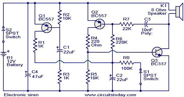
This is a compact electronic siren circuit based on three transistors. This circuit is suitable for incorporation with other alarm or siren projects such as burglar alarms, automatic factory sirens, or a simple push-to-on alarm. The electronic siren circuit...
This circuit is a sound generator designed to simulate the siren of a British police car. It utilizes two timer IC 555 components to produce sound frequencies. The operation of the circuit involves the 555 timer on the right,...
The 555 timer on the right is configured as an alarm sound generator, while the second 555 timer on the left operates as a 1 Hz astable multivibrator. The output from the left timer modulates the frequency of the...
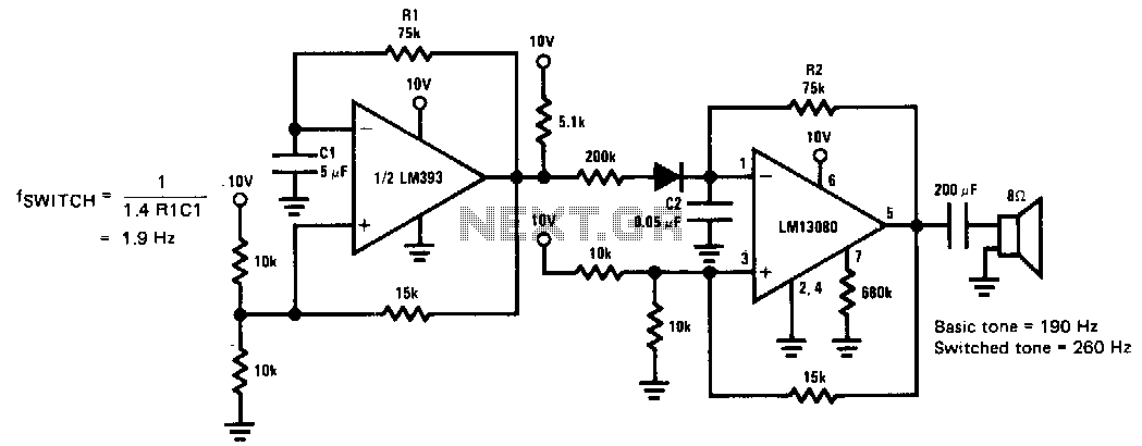
This siren provides a constant audio output while alternating between two distinct tones. The LM13080 is configured to oscillate at a fundamental frequency. This frequency can be modified by connecting a 200 kΩ charging resistor in parallel with the...
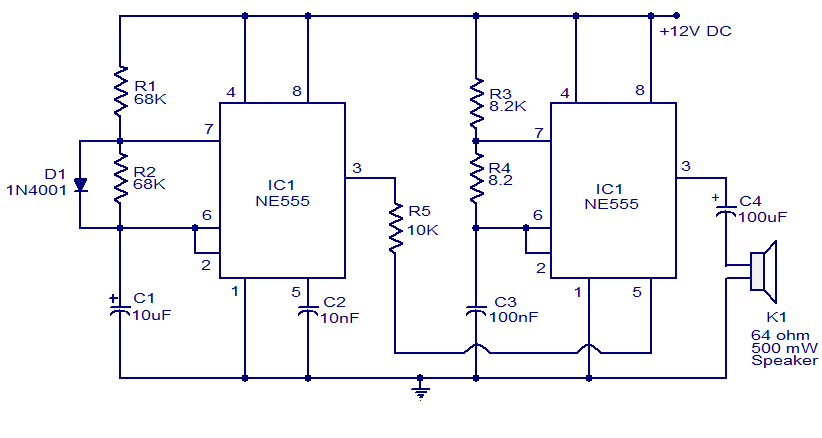
A variety of electronic circuits utilize the NE555 timer integrated circuit (IC). The circuit diagram presented illustrates a police siren based on two NE555 timer ICs, both configured as astable multivibrators. The circuit operates on a DC voltage supply...