
One kind of wireless remote control circuit

The remote control transmitter design integrates a dual-tone multi-frequency (DTMF) generator with an FM transmitter to enable wireless communication. The DTMF generator, implemented using the UM91214B IC, produces specific frequency tones corresponding to the keys pressed on a telephone keypad. This IC is designed for low power operation, making it suitable for battery-powered devices. The 3V power supply is stabilized by the zener diode D1, ensuring consistent voltage levels for reliable operation of the DTMF generator.
The FM transmitter section of the circuit is constructed around a transistor (T1), which acts as the main amplification element. The tuning circuit, consisting of the inductor (L1) and the variable capacitor (VC1), is crucial for determining the transmission frequency. The inductor and capacitor form a resonant LC circuit, allowing the transmitter to operate at the desired frequency range for effective signal transmission. The variable capacitor enables fine-tuning of the frequency, accommodating for any shifts due to component tolerances or environmental factors.
Additional components may include resistors and capacitors for biasing and stabilization of the transistor, as well as any necessary coupling capacitors to interface the DTMF output with the FM transmitter input. The overall design emphasizes compactness and efficiency, making it suitable for remote control applications where space and power consumption are critical factors. The integration of the DTMF generator with the FM transmitter allows for seamless communication, enabling users to send commands wirelessly with the press of a button.The remote control transmitter is composed of the DTMF generator and the FM transmitter circuit. Here we use one piece of UM91214B phone specific IC to produce the DTMF signal, the 3V power supply voltage is supplied by the 3V zener tube D1.The transmitter circuit is composed of the transistor T1 and the external circuits, the tuning circuit L1 and VC1 is.. 🔗 External reference
Related Circuits
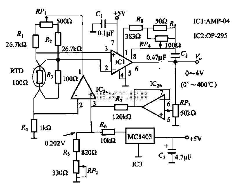
AMP-04 is a single-supply, single resistor gain adjustment circuit with an input voltage drift of less than 150 pV, a current drift of 5 nA, and a temperature drift of 8 pA/°C. The gain nonlinearity is 0.005% of the...
The circuit does not fail under slight variations, even if the input/output electric current characteristics are exceeded. Failure occurs only during a short circuit or extreme conditions at the output. The operation of the circuit is explained as follows:...
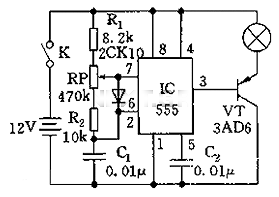
The circuit illustrated in the figure is a dimmer using the 555 timer as the core component. The 555 timer, along with resistors R1, RP, R2, and capacitor C1, forms an astable multivibrator. The oscillation frequency, f, is calculated...
The first time a user signs into developerWorks, a profile is created. Certain information in the profile, including name, country or region, and company, is publicly displayed and will accompany any content posted. Users have the option to update...
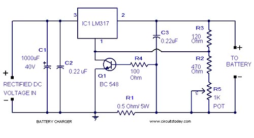
A simple lead-acid battery charger circuit with a diagram and schematic using the IC LM317, which provides the correct battery charging voltage. This lead-acid battery charger should be supplied with an input of 18 volts to the IC. The lead-acid...
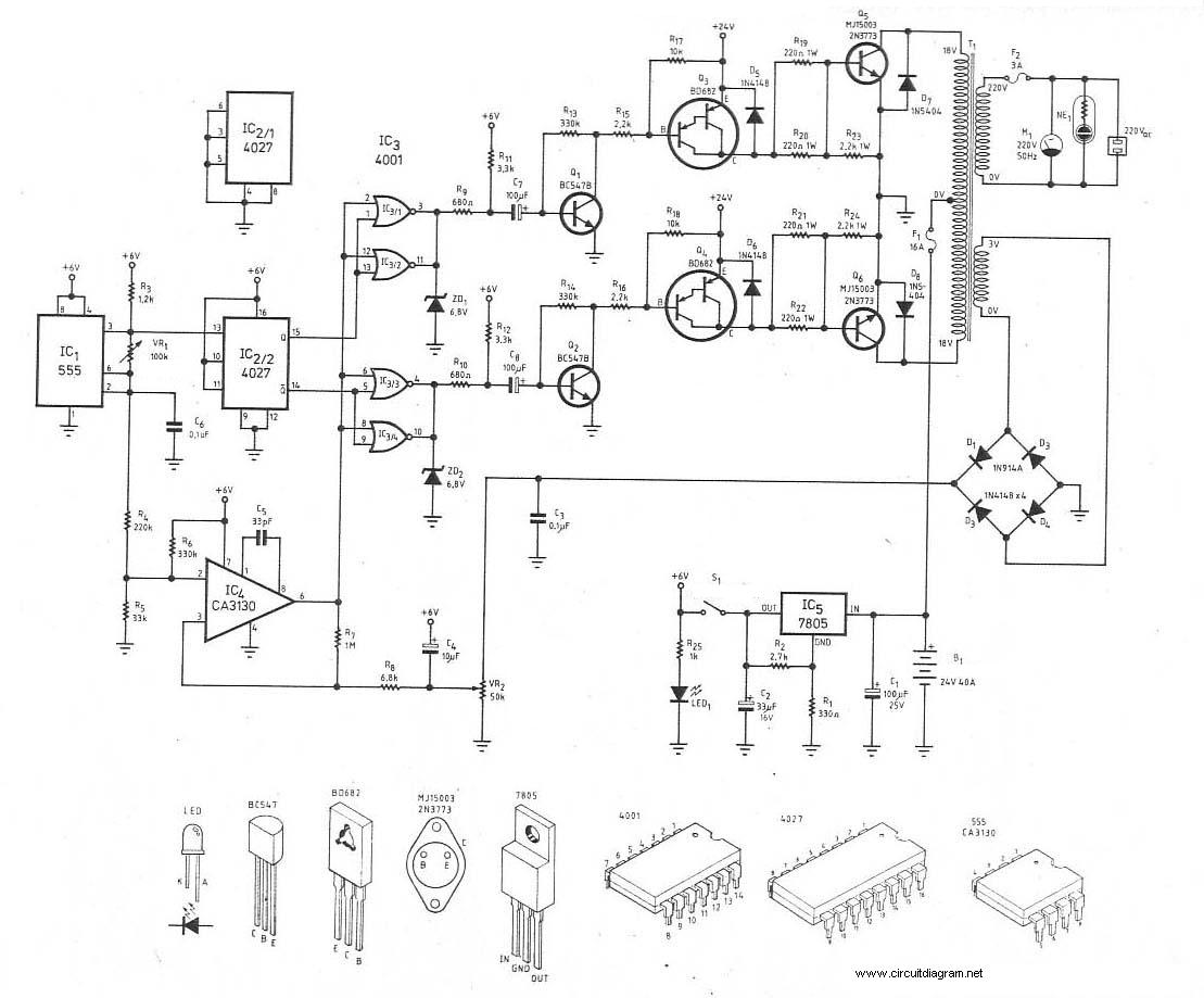
This is the schematic diagram of a 300W power inverter circuit. The inverter utilizes the MJ15003 power transistor for final amplification. If the MJ15003 transistor is difficult to source, it can be replaced with a 2N3773. The inverter is...