
Lead Acid Battery Charger Circuit

The lead-acid battery charger circuit utilizes the LM317 voltage regulator IC, which is known for its adjustable output voltage capabilities. The circuit is designed to provide a stable charging voltage suitable for lead-acid batteries, typically in the range of 13.8 to 14.4 volts, depending on the specific battery type and charging requirements.
The circuit configuration consists of the LM317 IC, several resistors, and capacitors to stabilize the output voltage and improve performance. The input voltage of 18 volts is supplied to the LM317, which regulates this voltage down to the desired charging voltage. The output voltage is adjustable by using two resistors (R1 and R2) connected to the adjustment pin of the LM317. The values of these resistors can be chosen based on the formula provided in the LM317 datasheet, which allows for precise control of the output voltage.
Additionally, it is advisable to include input and output capacitors (typically 0.1µF and 10µF) to filter any noise and ensure stable operation. A heat sink may be necessary for the LM317, as it can generate heat during operation, especially when there is a significant difference between the input and output voltages.
This charger circuit is suitable for charging small to medium-sized lead-acid batteries and can be used in various applications, including automotive and backup power systems. Proper safety measures should be observed when working with lead-acid batteries, as they can emit gases and require proper ventilation during charging.A simple lead acid battery charger circuit with diagram and schematic using IC LM 317,which provides correct battery charging voltage. This lead acid battery charger should be given an input 18 Volts to IC.. 🔗 External reference
Related Circuits
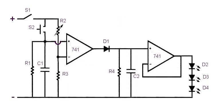
This circuit is designed for a project utilizing a 6V, 400 mA DC power supply. The open-circuit voltage is specified, indicating the voltage measured when no load is connected. The circuit employs a regulated 6V power supply, which is essential...
The FM modulator circuit, which utilizes frequency modulation, is constructed using a Motorola MC1648P oscillator. Two varactors, specifically Motorola MV-209, are employed to modulate the frequency of the oscillator. A 5000-ohm potentiometer is incorporated to bias the varactors for...
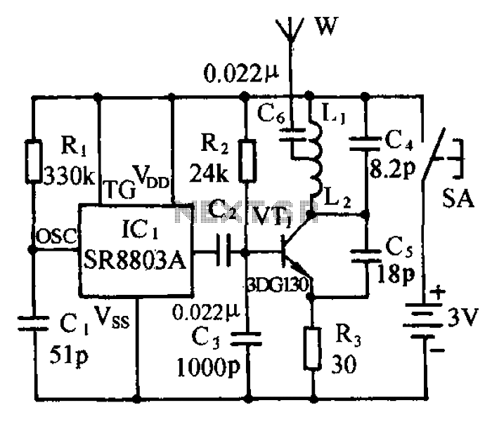
The circuit consists of a language and sound FM transmitter. It is mounted on a 25mm x 35mm PCB, designed to be placed on a table. When activated by pressing the micro switch SA, the circuit transmits an FM...
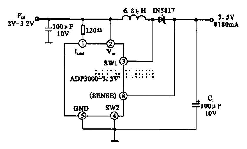
Boost 3.5V regulator circuit. This chip can boost or create a stable voltage supply from approximately 3V DC to a DC voltage of 3.5V. The boost regulator circuit is designed to increase a lower DC voltage, specifically from around 3V...

This circuit is an active filter designed for subwoofers, featuring a 24 dB per octave Bessel filter with a cutoff frequency of 200 Hz. It is suitable for those interested in experimenting with audio circuits in the subwoofer frequency...
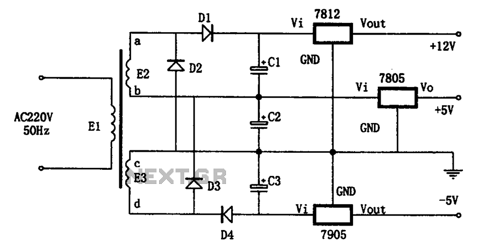
The circuit illustrated in the figure represents a specialized power supply configuration. It is straightforward in design and can be constructed using two identical secondary windings to generate three distinct DC voltage outputs: +5V, -5V, and +12V. The circuit...