
Only one-way operation of the automatic control circuit of the motor

The described circuit employs a phase sequence detector to ensure that the motor operates correctly under varying conditions. The neon bulb serves as an indicator of the phase sequence status; when it is illuminated, it signifies that the phase sequence is incorrect. The relay (KA) acts as a safety mechanism, preventing the motor from starting if the phase sequence is not as required. The use of two relays, KA and KMz, allows for a fail-safe operation: KA ensures that the motor does not start under incorrect conditions, while KMz provides a means to maintain motor operation even when the phase sequence is altered.
This circuit can be particularly beneficial in industrial settings where motors are frequently subjected to changes in power supply conditions. By implementing this phase sequence control mechanism, the risk of equipment damage is significantly reduced, and operational reliability is enhanced. The design should ensure that all components, such as relays and indicators, are rated for the specific voltage and current levels associated with the motor and power supply to maintain safety and efficiency. Proper installation and regular maintenance of this circuit will contribute to its longevity and the overall safety of the motor operation.In some places, allowing only a specific direction by the motor running, even when the power supply phase sequence for some reason (such as outside line after overhaul wrong) while inverted, but also to ensure that the motor running in the specified direction. Otherwise, it will cause physical and equipment do so. The phase sequence can be used for this determination is to be controlled. Circuit shown in Figure 3-90. When the power supply phase sequence is correct, that is, U, V, W phase sequence when, Ne neon bulb does not light, relay device KA pull, press the start button SBi, contact KMi pull the motor starts running forward.
If the power supply phase sequence right, Ne shiny, KA released. Press SBi, KMz suction units, the motor will change the phase sequence followed by people power, the motor still running forward start.
Related Circuits
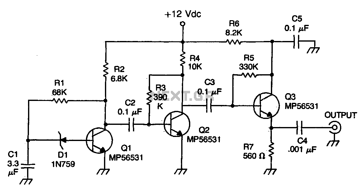
The Zener diode functions as an avalanche rectifier in reverse bias mode, connected to the input circuit of a wideband RF amplifier. The noise is amplified and subsequently applied to the cascade wideband amplifier, utilizing transistors Q2 and Q3. The...
An SMS-based home appliance control system is being developed using the ATtiny2313 microcontroller. There are issues with programming the microcontroller. The SMS-based home appliance control system utilizes the ATtiny2313 microcontroller, which is a versatile 8-bit microcontroller from the AVR family....

This is a BTL (bridged tied load) mono amplifier with a DC volume control circuit. This circuit utilizes the TDA7052A/AT, which is suitable for monitors, TVs, and battery-operated portable radios and recorders. Unlike conventional DC volume circuits, the TDA7052A/AT...
This circuit is similar to the previous one but employs positive feedback to enhance the amplitude delivered to the speaker. It was adapted from a small five-transistor radio that utilizes a 25-ohm speaker. In the prior circuit, the load...
This simple circuit can be used to charge a pair of AA or AAA-sized cells using solar energy. It has been utilized to maintain the operation of devices such as a Palm Pilot and a Walkman radio continuously. This...
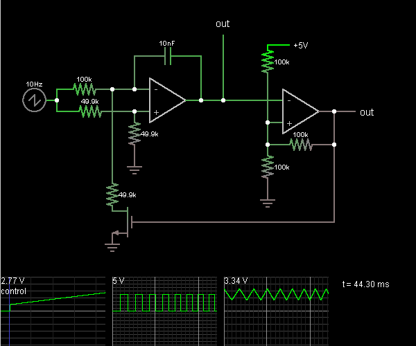
This circuit is a voltage-controlled oscillator, which is an oscillator whose frequency is determined by a control voltage. A 10 Hz sawtooth oscillator provides the control voltage in this case; this causes the frequency to rise slowly until it...