
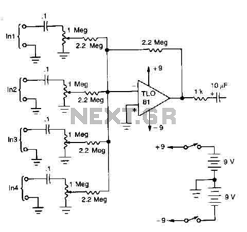
op amp 6 line audio mixer circuit

The audio mixer circuit is designed to manage multiple audio inputs and provide a single output with minimal distortion and noise. The architecture typically includes a series of operational amplifiers (op-amps) configured to amplify the audio signals from various sources, such as microphones and line-level devices. The initial stage of the mixer consists of mic preamps, which are crucial for boosting the low-level signals from microphones, typically around 2mV RMS. These preamps provide a gain of approximately 40dB, ensuring that the microphone signals are adequately amplified for further processing.
Following the preamp stage, the mixer employs a summing amplifier. This component is essential for combining the multiple audio signals into a single output. The summing amplifier is designed with a gain of 2 or 6dB, which compensates for any losses incurred during the mixing process. The final output of the mixer, therefore, achieves a total gain of 46dB, making it suitable for driving further audio processing equipment or amplification stages.
The choice of op-amps is flexible, allowing for various types, including bipolar, FET input, and MOS types. Commonly used op-amps in this application include the 741, LF351, TL061, TL071, and CA3140. This flexibility in component selection enables designers to optimize the circuit for specific performance characteristics, such as noise figure or bandwidth.
For power supply requirements, the mixer circuit operates on a dual positive and negative voltage supply. This can be accomplished using two 9-volt batteries or a dedicated power supply, which is recommended for extended use. Proper power supply design is critical to ensure that the op-amps function correctly and maintain audio fidelity throughout the mixing process.
Overall, this audio mixer circuit provides a robust solution for combining multiple audio signals while maintaining high-quality performance, making it suitable for various audio applications, including live sound reinforcement, recording, and broadcasting.As with any audio mixer circuit, a slight loss is always introduced. The final summing amplifier has a gain of 2 or 6dB to overcome this. The Input line level should be around 200mV RMS. The mic inputs are amplified about 100 times or 40dB, the total gain of the mixer including the summing amplifier is 46dB. The mic input is designed for microphon es with outputs of about 2mV RMS at 1 meter. Most dynamic microphones meet this standard. The choice of IC op-amp is not critical in this circuit. Bipolar, FET input or MOS type op-amps can therefore be used; i. e 741, LF351, TL061, TL071, CA3140 etc. The power supply is a dual positive and negative supply, two 9 Volt batteries may be used as shown above or a power supply is recommended for longer periods of use 🔗 External reference
Related Circuits
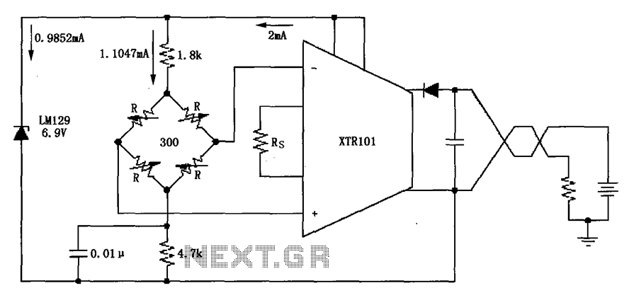
The circuit utilizes the LM129 voltage regulator to produce a 6.9V voltage reference, supplying a current of 1.0147mA from the 6.9V reference voltage to the bridge. The bridge may consist of varistor-type pressure sensors. The LM129 voltage regulator is a...
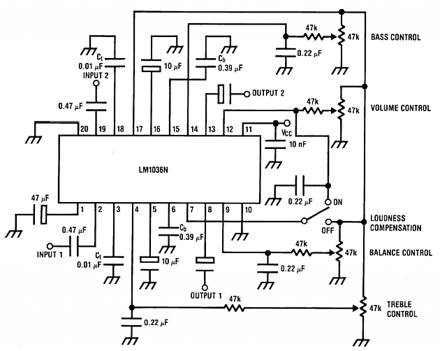
The LM1036 is a DC-controlled circuit designed for managing tone (bass/treble), volume, and balance in stereo applications, such as car radios, televisions, and audio systems. It features an additional control input for easy loudness compensation. Four control inputs allow...
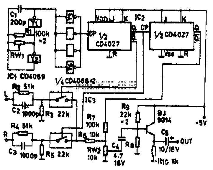
The circuit schematic diagram features IC1 (4069) and components Y1 and Y2, which together form a frequency oscillator operating at 76 kHz. Components Y3 to Y6 provide isolation and shape the output into the IC2 (CD4027) dual JK flip-flop,...
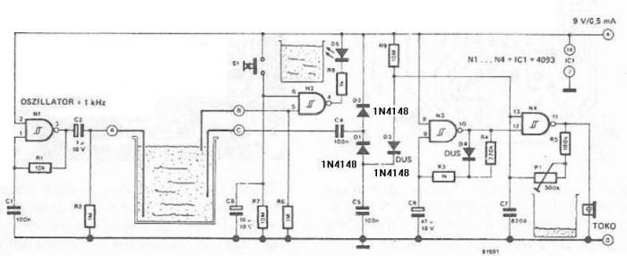
The circuit diagram is straightforward and operates as follows: the N1 Schmitt trigger functions as an oscillator, producing a frequency of approximately 1 kHz. When there is sufficient water in the tank, alternating voltage flows from electrode A to...
A TL081 operational amplifier is utilized as a high impedance to low impedance converter and as a signal mixer. The input impedance is approximately 1 megohm, while the output impedance is around 1 kohm. The circuit is powered by...
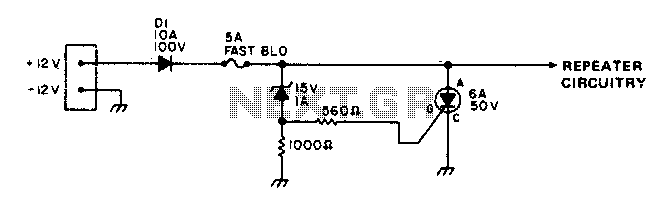
To protect portable emergency power repeaters from reverse or excessive voltage, diode D1 prevents damage from incorrect polarity, while the zener diode voltage sets the maximum voltage that can reach the rest of the circuitry. Additionally, a fast-blowing fuse...