
XTR101 bridge input voltage excitation circuit diagram

The LM129 voltage regulator is a precision device designed for generating stable reference voltages. In this circuit, it is configured to output a nominal voltage of 6.9V, which is crucial for ensuring accurate readings from the connected sensors. The output current of 1.0147mA is specifically chosen to meet the requirements of the bridge sensor without exceeding its operational limits, thereby ensuring reliable performance.
The bridge sensor in this application is likely a varistor-type pressure sensor, which utilizes the principle of resistance change under varying pressure conditions. These sensors are known for their sensitivity and fast response times, making them suitable for applications requiring precise pressure measurements. The bridge configuration allows for differential measurements, which enhances the accuracy of the readings by canceling out common-mode noise and other interferences.
Additionally, the circuit may include passive components such as resistors and capacitors to filter noise and stabilize the voltage output. Proper layout and grounding techniques should be employed to minimize electromagnetic interference (EMI), which can affect the performance of the voltage reference and the sensor readings.
In summary, the integration of the LM129 voltage regulator with a varistor-type bridge sensor in this circuit provides a robust solution for generating a stable voltage reference and accurate pressure measurements, essential for various applications in electronics and instrumentation. As shown, the circuit uses the LM129 regulator to generate 6.9V voltage reference, provided 1.0147mA current from 6.9V reference voltage to the bridge. Bridge may be as pressur e sensors varistor-type bridge sensor.
Related Circuits
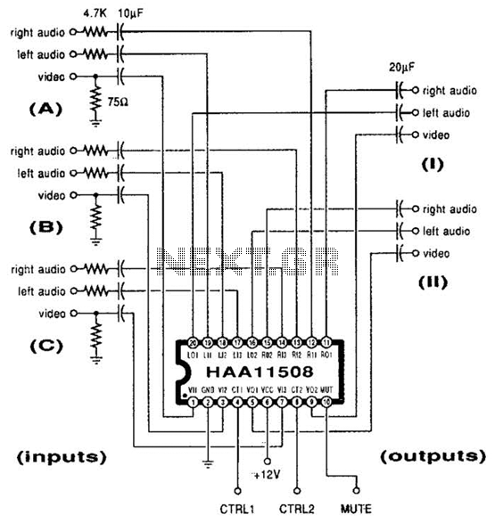
This channel selector selects video and stereo audio from any one of three different sources. The circuit should be constructed on a PC board with plenty of ground plane to minimize noise. The channel selector circuit is designed to facilitate...
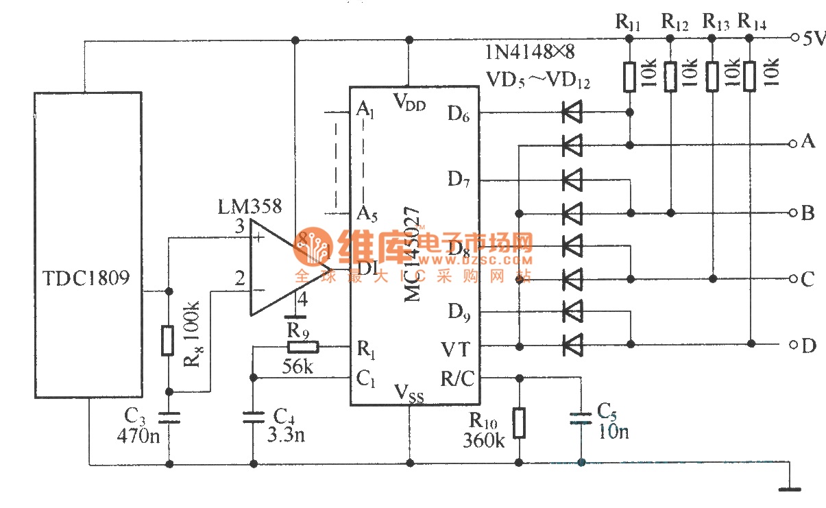
The TDC1808/TDC1809 is a pair of wireless remote control transmitter and receiver components. They utilize an internal antenna to transmit both digital and analog signals. These components are suitable for various wireless remote control devices. Key features include compact...
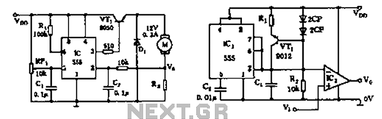
The circuit consists of a 555 motor automatic governor configuration. It includes flip-flops, a 555 timer, and a switching tube. A sampling circuit is formed by connecting R7 and the motor in series. RP1 is used to control the...
This is a differentiator circuit. This circuit can be used to perform differential operations. There are two types of differentiators: the true differentiator and another type. A differentiator circuit is designed to output a voltage that is proportional to the...
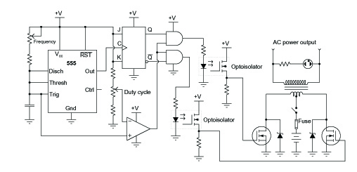
A common topology for DC-AC power converter circuits employs a pair of transistors to switch DC current through the center-tapped winding of a step-up transformer. Examine the check plot images from a PCB drafting program for a control board...
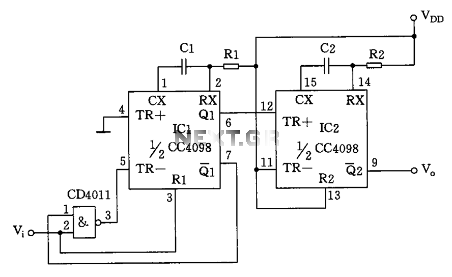
The circuit depicted features a double oscillator utilizing a monostable multivibrator CC4098 and a quad 2-input NAND gate CC4011, among other components. This circuit allows for adjustable frequency and duty cycle. It is primarily designed as a keying oscillator,...