
Op-Amp Application: Level Shifting Amplifier

In linear circuit design, the process of amplifying a voltage that is referenced to a specific DC level is crucial for various applications, such as signal conditioning, audio amplification, and sensor interfacing. This involves using operational amplifiers (op-amps) configured in a non-inverting or inverting amplifier configuration, depending on the desired gain and output characteristics.
The op-amp receives an input voltage (V_in) that is offset by a DC bias voltage (V_ref). The output voltage (V_out) is then expressed as a function of the input voltage and the gain determined by external resistors. In a non-inverting configuration, the gain (A) can be calculated using the formula A = 1 + (R_f/R_in), where R_f is the feedback resistor and R_in is the input resistor. The output voltage can be represented as V_out = V_ref + (V_in * A).
It is essential to ensure that the op-amp operates within its specified voltage range to avoid saturation and distortion of the amplified signal. Additionally, considerations such as bandwidth, slew rate, and power supply requirements must be taken into account when designing the circuit.
The output can then be used in various applications, including driving loads, interfacing with analog-to-digital converters, or further processing in subsequent stages of a more complex electronic system. Proper filtering and decoupling techniques should be implemented to minimize noise and ensure stable operation of the amplifier circuit.Sometimes, in linear equipment design, it`s necessary to take a voltage which is referred to some dc level and generate an amplified output which is referred.. 🔗 External reference
Related Circuits
This is a specialized low-voltage version of an audio preamplifier. The emitter voltage of transistor T1 is biased close to half the supply voltage (1.5V) to enable maximum output voltage swing. Both transistors are directly coupled and utilize closed-loop...
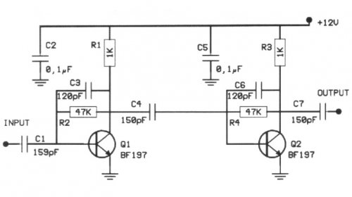
The following circuit illustrates a 20 dB VHF amplifier circuit diagram utilizing the BF197 transistor. Features include a simple circuit design. The 20 dB VHF amplifier circuit is designed to amplify very high frequency signals, making it suitable for applications...
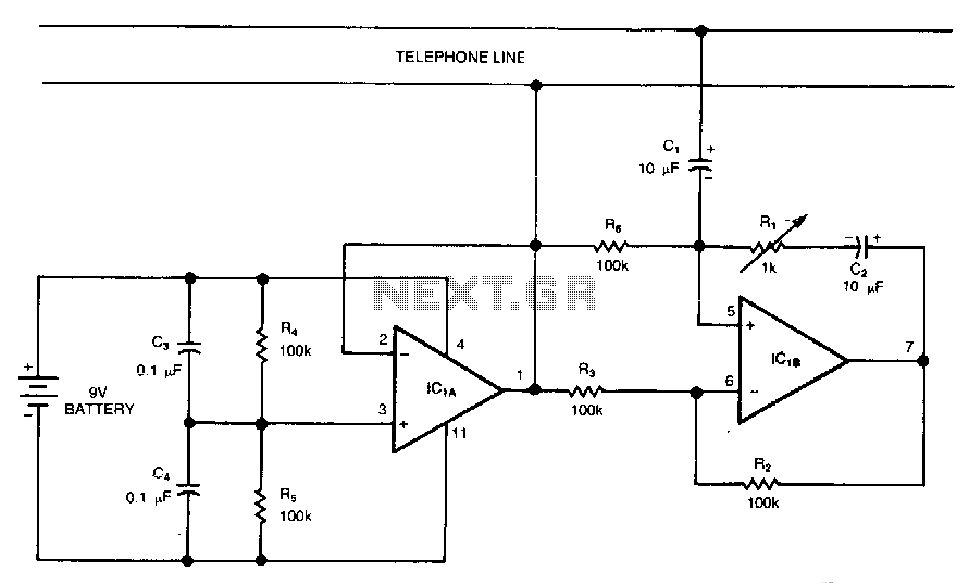
This circuit is a bidirectional amplifier capable of amplifying both signals in a duplex telephone conversation. It operates on the principle of negative resistance. While such an amplifier may be prone to instability, adjusting the load resistor (Rl) can...
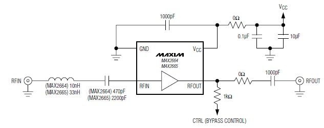
These devices feature a broadband low-noise amplifier (LNA) with an integrated bypass switch. The MAX2664 operates within the UHF frequency range of 470 MHz to 860 MHz, while the MAX2665 functions within the VHF frequency range of 75 MHz...
The sound system features a de-sensitized design with a maximum range that can be increased if desired. It includes two tone controls: one offering a lift of 10 dB and the other providing a subtle cut of 3 dB....
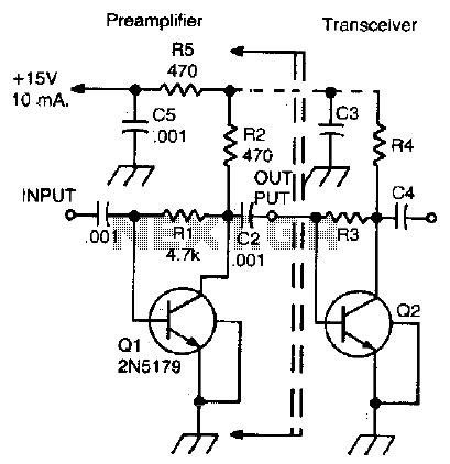
This simple, inexpensive, wideband RF amplifier provides 14 dB gain on two meters without the use of tuned circuits. The RF amplifier described operates within the two-meter band, which typically spans frequencies from 144 to 148 MHz. It is designed...