
op amp based sound detector circuit

This sound detection circuit utilizes a condenser microphone, which is known for its high sensitivity due to its powered nature. The microphone captures sound waves from the surrounding environment and converts them into an electrical signal. This signal is then amplified by the 741 op-amp, which is configured as an inverting amplifier. The inverting configuration allows for the manipulation of the signal phase, effectively inverting the output signal compared to the input.
Resistor R1 plays a crucial role in setting the gain of the op-amp, thus allowing for fine-tuning of the circuit's sensitivity to sound. By adjusting R1, the user can optimize the circuit for various sound levels, ensuring reliable detection in different environments. The capacitors C1 and C2 serve to filter out any unwanted DC offset that may be present in the signal, allowing only the alternating current (AC) component, which contains the sound information, to pass through to the output stage.
The output transistor Q1 is responsible for driving the subsequent alarm or notification circuit. The output signal taken from the collector of Q1 will be an inverted version of the amplified signal from the op-amp, which may need to be considered when interfacing with other components in the system. Overall, this circuit is an effective solution for sound detection applications, particularly in security systems where timely alerts are essential.This is a circuit that can be used for detecting sounds and providing an output signal when a sound is detected. This output signal may be fed to another circuit that sets off an alarm when the signal is received. This circuit is therefore useful in security applications. This is the figure of the circuit; The circuit uses a condenser microphone t o pick up sounds from the environment. This is a powered microphone, which makes it more sensitive than ordinary microphones. The microphone transforms the sound waves into an electronic signal that is fed to the 741 op amp. The 741 op amp in this circuit is configured as a single-supply inverting amplifier. Adjust R1 to maximize the sensitivity of your circuit. C1 and C2 are used to block the DC component of the signals, so that only the AC component carrying the sound information reaches the output transistor Q1. Note that the output, which is taken from the collector of Q1, is inverted with respect to the output of the 741 amplifier.
🔗 External reference
Related Circuits

This smoke detector electronic project is designed using the LM1801 and common electronic components. The smoke detector circuit diagram does not utilize ionization detection, gas sensors, or optocouplers; instead, it employs two photoresistors (LDRs) and an LED. The circuit...
This circuit employs an HgCdTe demodulation device that can be cooled to 77K using liquid nitrogen. It utilizes a constant current bias for the demodulation device, which is connected to the input port. The voltage amplification factor is 200,...
A high-input-resistance op-amp, a bridge rectifier, a microammeter, and a few other discrete components are all that are required to realise this versatile circuit. This circuit can be used for measurement of dc, ac rms, ac peak, or ac...
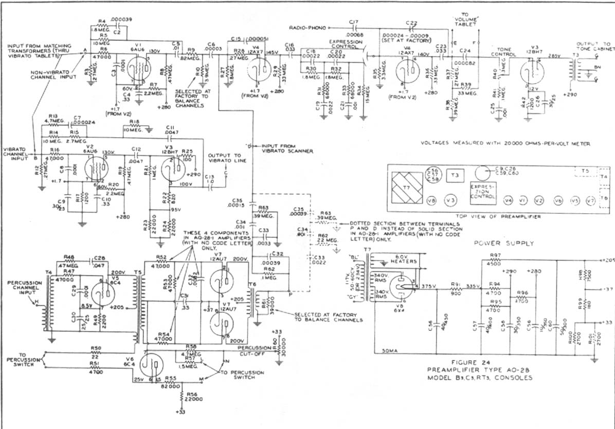
Construct a preamplifier intended to accept a 1/4" keyboard line-level signal and drive a Leslie 147 amplifier. The preamp will utilize a 12AX7 and 12BH7, following the design of a Hammond Organ preamp. The focus will be on the...
This code lock circuit is an electronic combination lock designed for daily use. It only responds to the correct sequence of four digits entered remotely. If an incorrect key is pressed, the lock resets. The lock code can be...
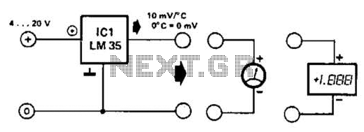
An effective temperature sensor circuit is designed to receive power from a 4-to-20 mA loop without impacting the loop current. The temperature sensor integrated circuit (IC) used is the AD590F, which operates with a supply voltage ranging from 4...