
Simple Code Lock Circuit

The electronic combination lock circuit operates by utilizing two CD4013 dual-D flip-flop ICs to store the state of the entered digits. The configuration involves connecting the clock pins of the flip-flops to designated input pads, which receive signals from the keypad. Each time a correct digit is entered in the specified sequence, the corresponding flip-flop is triggered, changing its state and passing the signal to the next flip-flop in line. This cascading effect continues until the final flip-flop is reached, where the output determines whether the relay is activated.
The relay, controlled by the output of the last flip-flop, serves as a mechanism to engage or disengage the device being secured, such as a vehicle ignition system. The reset functionality is critical; it ensures that any incorrect entry resets the entire system, preventing unauthorized access. The reset switches allow for immediate reconfiguration of the system, enabling users to enter a new code if necessary.
To check the proper operation of this code lock circuit, a systematic approach can be employed. First, ensure that all connections are secure and that the power supply is functioning correctly. Use a multimeter to verify voltage levels at different points in the circuit, particularly at the clock and output pins of the flip-flops. Test each keypad switch individually to confirm that pressing a key appropriately changes the state of the flip-flop.
For further evaluation, simulate entering the correct sequence and observe the output at the relay. If the relay activates as expected, the circuit is functioning correctly. In contrast, if the relay does not activate, reevaluate the connections and the sequence of inputs. Additionally, it may be beneficial to incorporate a logic analyzer to visualize the timing and state changes within the flip-flops to ensure proper operation.
This circuit can be adapted for various applications beyond automotive use, including secure entry systems for buildings or electronic safes, showcasing its versatility in enhancing security measures through electronic means.This simple code lock circuit described here is of an electronic combination lock for daily use. It responds only to the roght sequence of four digits that are keyed in remotely. If a wrong key is touched, it resets the lock. The lock code can be set by connectiong the line wires to the pads A, B, C and D in the figure. For example, if the code is 1756, connect line 1 to A, line 7 to B, line 5 to C, line 6 to D and rest of the lines-2, 3, 4, 8 and 9 to the reset pad as shown by dotted lines in the schematic. The code lock circuit is built around two CD4013 dual-D flip-flop ICs. The clock pins of the four flip-flops are connected to A, B, C and D pads. The correct code sequence for energisation of relay RL1 is realised by clocking points A, B, C and D in that order.
The five remaining switches are connected to reset pad which resets all the flip-flops. Touching the key pad switch A/B/C/D briefly pulls the clock input pin high and the state of flip-flop is altered. The Q output pin of each flip-flop is wired to D input pin of the next flip-flop while D pin of the first flip-flop is grounded.
If correct clocking sequence is followed then low level appears at Q2 output of IC2 which energises the relay through relay driver transistor T1. The reset keys are wired to set pins 6 to 8 of each IC. (Power-on-reset capacitor C1 has been added at EFY during testing as the state of Q output is indeterminate during switching on operation.
) This simple code lock circuit can be usefully employed in cars so that the car can start only when the correct code sequence is keyed in via the key pad. The code lock design can also be used in various othee application. i have made the circuit but i need the idea how to check its proper operation i. e how this code is taken by an encoder and help in accessing its application can you please send me more detailed information of the circuit I really need this for our project.
and also send the working process of the circuit to my mail id 🔗 External reference
Related Circuits
This is a silicon transistor circuit showing typical voltage values. When the forward base/emitter voltage is 0.6 to 0.7 V, the transistor is silicon. Germanium transistors will have a forward base/emitter bias voltage of 0.2 to 0.3 V. This...
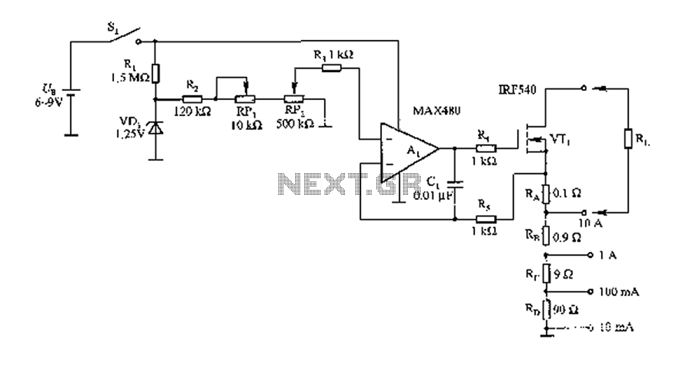
The FIG load test is a control circuit designed for external loads up to 10A, commonly utilized in drive test power applications, power amplifiers, LED solenoids, and relays. It is capable of handling various resistive loads and features a...
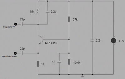
This circuit is designed to enhance RF signals from a television antenna operating at UHF frequencies in the range of 450-800 MHz. It provides a gain of approximately 10 dB, making it suitable for boosting weak TV signals. The...
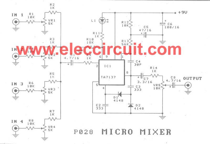
A micro mixer circuit is designed to be simple, affordable, compact, and versatile. This circuit can mix up to four input channels, including microphone signals, FM tuners, AUX, and other signals, as illustrated in Figure 1. The operation begins...
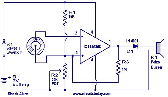
This is a simple shock-sensitive alarm circuit with numerous applications, ranging from home use to automobiles. The primary application of this circuit is as an anti-theft alarm for vehicles. A piezoelectric sensor is employed as the shock sensor and...
Colour TV Camera Tutorial - Block Diagrams - Electronics Circuit and Tutorials - Hobby Science Projects - Modulation allows low-frequency audio signals to be transmitted over long distances. This is achieved by superimposing the low-frequency audio signal onto a...