
Op amp F003 composition of automatic exposure timer circuit

The F003 circuit is designed to provide a reliable and efficient automatic timer for photographic applications. At its core, the circuit utilizes two operational amplifiers: A1, which acts as an integrator, and A2, which functions as a comparator. The integrator (A1) accumulates the input voltage signal (V1) from the silicon photocell (2CR), which detects light levels. The output of A1 is a ramp voltage that increases over time, reflecting the cumulative light exposure.
The comparator (A2) continuously monitors the output from A1 against a predetermined threshold voltage, Ems. This threshold is adjustable via a 10k potentiometer, allowing users to customize the sensitivity of the exposure control. When the ramp voltage from A1 reaches this threshold, the comparator output transitions to a high state, signaling that the set exposure time has been reached. This transition activates transistor VT, which is configured to drive a relay. The relay can control additional loads such as lamps or cameras to stop the exposure process automatically, ensuring that the exposure is neither too short nor too long.
The circuit's design also incorporates manual control features, allowing users to bypass the automatic function if desired. A switch enables selection between automatic and manual modes, providing flexibility based on user preference or specific photographic requirements. Additionally, a reset button is included for the integrator, allowing the user to clear the accumulated charge and restart the timing process as needed.
This operational amplifier-based timer circuit exemplifies a practical application of analog electronics in photography, combining the principles of integration and comparison to achieve precise exposure control in automated systems.As shown in Figure II F003 is versatile photographic constituent operational amplifier amplifying automatic timer circuit. Operational amplifier A1 composition integrator operational amplifier A2 composed of comparators. 2CR silicon photocell voltage is generated by the integrator input signal V1, the signal input from the pin , Al output voltage with the reference voltage to the comparator comparison. When the output voltage is equal to the upper limit threshold voltage comparator Ems, A2 comparator output is high, the transistor VT conduction, relay, lamp, and the end of exposure, exposure time so as to achieve automatic control purposes.
Ems by a 10k potentiometer setting, the exposure time T = R1C1Ems / V1. S switch to automatic, manual switch. AN integrator reset button for the switch.
Related Circuits
Simple electronics provides the foundation for many closed loop control systems. Since the principle components that we would wish to control for HSP are electronic in nature, an electronic control system is the natural choice. As this document is...
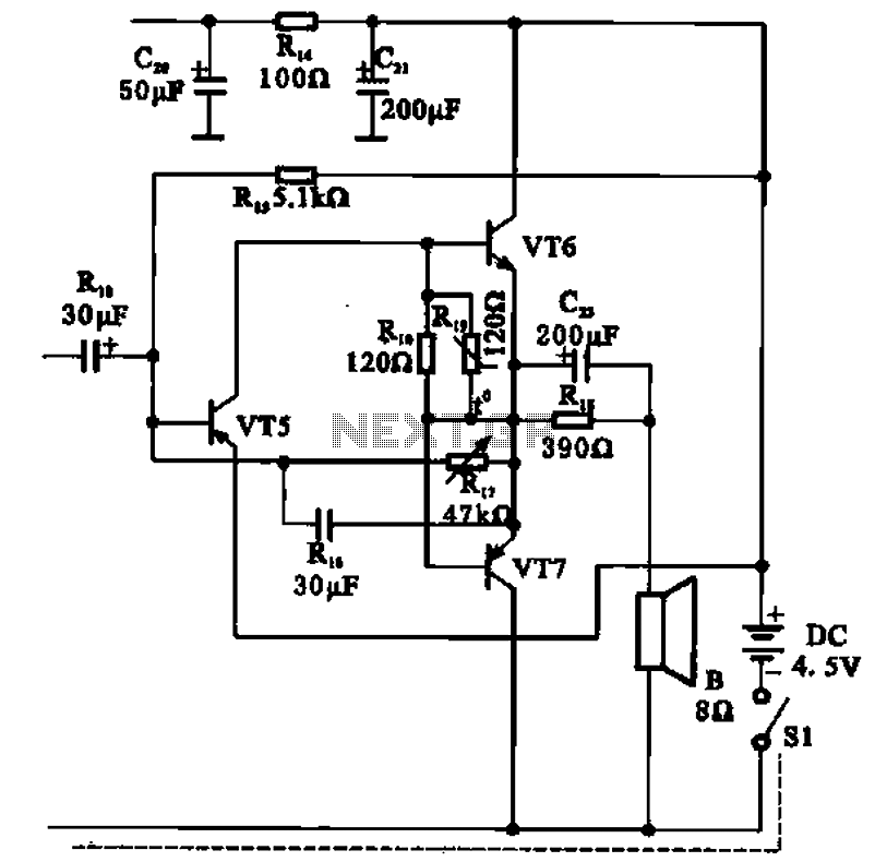
The transistor radio features a common output transformerless (OTL) power amplifier circuit. The VT5 component serves as the bias resistor for the driver stage. VT6 and VT7 form a complementary symmetry configuration, with VT6 being a germanium NPN transistor...
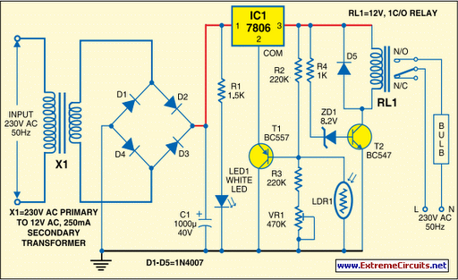
Voltage regulator ICs (78xx series) deliver a stable output voltage despite a fluctuating input supply when the common terminal is grounded. Any voltage above zero volts (ground) connected to the common terminal is added to the output voltage, meaning...
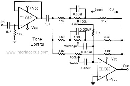
This topic continues the coverage of audio tone controls. The first entry started with a passive tone control circuit using different RC filter configurations and introduced an active filter. The second entry showed a fully designed 2-band active tone...
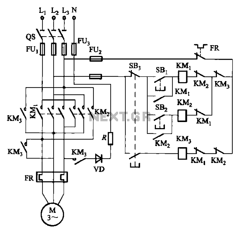
The circuit illustrated in Figure 3-145 employs a rectifier diode brake for neutral grounding in a three-phase, four-wire power supply system. This circuit design incorporates a rectifier diode brake, which plays a crucial role in ensuring the safety and reliability of...
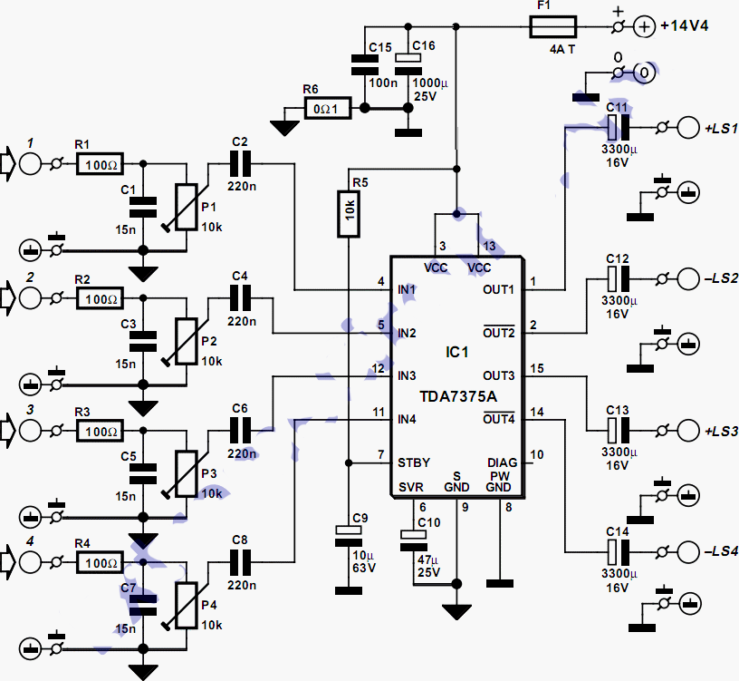
This quad amplifier is designed primarily for automotive use but can also be applied in various medium-power scenarios. The TDA7375A is suitable for situations requiring a reasonable amount of audio power with a relatively low supply voltage. It is...