
Forward and reverse operation of the dynamic braking circuit 2

This circuit design incorporates a rectifier diode brake, which plays a crucial role in ensuring the safety and reliability of a three-phase power supply system. The primary function of the rectifier diode is to convert alternating current (AC) from the power supply into direct current (DC), which is essential for maintaining a stable voltage level and preventing fluctuations that could damage connected equipment.
In a three-phase, four-wire system, the neutral wire serves as a return path for unbalanced loads, allowing for the effective distribution of power across the three phases. The rectifier diode brake is strategically connected to the neutral point to ground the system, which helps in stabilizing the voltage levels and provides a reference point for the system. This grounding mechanism is vital for protecting the circuit from overvoltage conditions and ensuring that any fault currents are safely diverted to the ground, thereby minimizing the risk of electrical shock or equipment damage.
The circuit's configuration may include additional components such as capacitors for filtering, resistors for current limiting, and possibly fuses for overcurrent protection. These elements work in conjunction to enhance the overall performance and safety of the power supply system. Proper sizing and rating of the rectifier diode are essential to handle the expected load currents and to ensure efficient operation without overheating or failure.
Overall, the implementation of a rectifier diode brake in a three-phase, four-wire power supply system is a critical aspect of electrical engineering that contributes to the efficient and safe operation of industrial and commercial electrical systems.1The circuit shown in Figure 3-145. The line uses a rectifier diode rectifier brake for neutral grounding of the three-phase four-wire power supply system.
Related Circuits
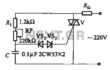
The introduction for a unidirectional thyristor trigger circuit is also applicable to the TRIAC. Several bidirectional circuits are illustrated in Figure 16-28. Figures 16-28 (a) and (b) depict a direct trigger circuit; Figure 16-28 (c) illustrates a dual diode...
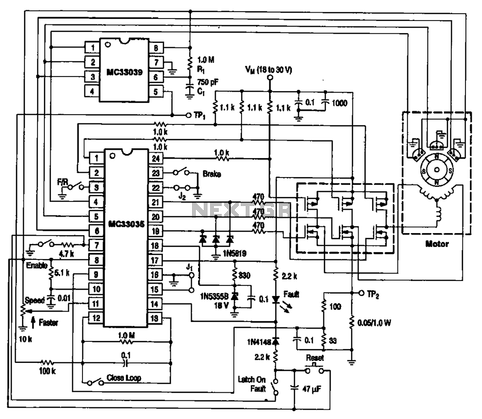
The brushless DC motor control circuit utilizing the MC33035 and MC33039 chips employs a combination of control circuits as illustrated in the figure. The primary components include the MC33035 motor control chip, the MC33039 brushless motor adapter, field effect...

This enhanced infrared detector is designed for use with commercial infrared remote control handsets. This compact circuit is effective for quick go/no-go applications. The infrared detector circuit is engineered to respond to signals emitted by infrared remote control devices, commonly...

This alarm circuit is designed to monitor a mains-powered smoke detector located in a shed used for dog kennels. It ensures complete isolation from the mains, allowing low-voltage (12V) cabling to connect to the alarm circuit situated inside the...

The circuit is designed to detect clogging in a wheat planter by utilizing light-emitting diodes (LEDs) and photodiodes. When the light path is obstructed by particles, the photodiode receives less light, causing the resistance of VD2 to increase. This...

A 555 timer configured as an astable multivibrator is used in this circuit to generate an audio note. The capacitance value can be changed to vary the audio note as desired. The circuit utilizes a 555 timer IC, which...