
op amp IR Demodulator Design

The circuit design for the IR demodulator focuses on detecting the presence of an IR signal modulated at a frequency of 32.678 kHz. The primary components include a series of resistors and capacitors that form a filtering and amplification stage, allowing for effective signal processing. The resistors R1, R2, and R3 are configured to set the gain and input impedance of the circuit, while capacitors C1, C2, and C3 serve to filter high-frequency noise and stabilize the signal.
The voltage sources, V1 and V2, provide the necessary biasing for the circuit, ensuring that the operational amplifier operates within its linear region. The pulse generator simulates the incoming modulated IR signal, which is critical for testing the circuit's response to actual IR signals.
The choice of the LT1722 operational amplifier is significant due to its high speed and low noise characteristics, which are essential for accurately demodulating the IR signal. The calculated gain of approximately 400 indicates that the circuit is designed to amplify weak IR signals to a detectable level. However, to maintain fidelity in the signal processing, the operational amplifier must have a GBWP of at least 14 MHz, which is essential for handling the 32.678 kHz modulation frequency effectively.
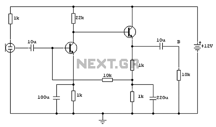
In summary, the IR demodulator circuit is designed with specific components and configurations to achieve reliable detection of IR signals. Proper selection of the operational amplifier and careful consideration of circuit parameters are crucial for successful operation. Further testing and refinement may be necessary to ensure the circuit functions as intended, particularly in the context of LTspice simulations and real-world applications.Designing an IR demodulator circuit to replace the one shown in this question. Basically I want to demodulate a simple IR signal modulated at 32. 678 kHz. I just need to know if the signal is present. No packets. Just IR present or not present. I have tried simulating this in LTspice with no success so I am not sure if I`ve done something ver y wrong in spice or in my circuit. I am no pro with LTspice. R1 N001 N006 2. 49K tol=1 pwr=0. 1 R2 Output N003 1Meg R3 N006 N005 1Meg C1 N005 N004 470pF C2 N003 N001 220pF C3 Output N001 220pF V1 N006 0 2. 5 V2 N002 0 5 V3 N004 0 PULSE(0. 05 0 0 0 0. 0000152587890625 0. 000030517578125 200) XU1 N005 N003 N002 0 Output LT1722. tran 12ms. lib LTC. lib. backanno. end The overall gain of the circuit is approximately 400 by my calculations. So, in choosing my op amp I would need a GBWP of 14 MHz or greater Any other critical op amp specifications for this application Note the amp showed is just a place holder until I choose the op amp.
🔗 External reference
Related Circuits
7W Mono Audio Amplifier Kit - This compact amplifier is designed around the TDA2003 integrated circuit, which can provide 7 watts of audio power into a 4-ohm load. The 7W Mono Audio Amplifier Kit utilizes the TDA2003 IC, a popular...
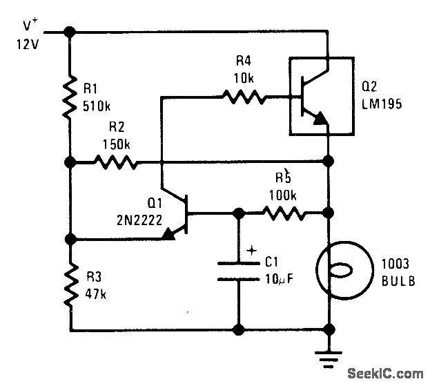
The National LM195 power transistor is activated and deactivated once per second to flash a 12-V lamp. The current limiting feature of the LM195 prevents high peak currents during turn-on, even when a cold lamp can draw up to...
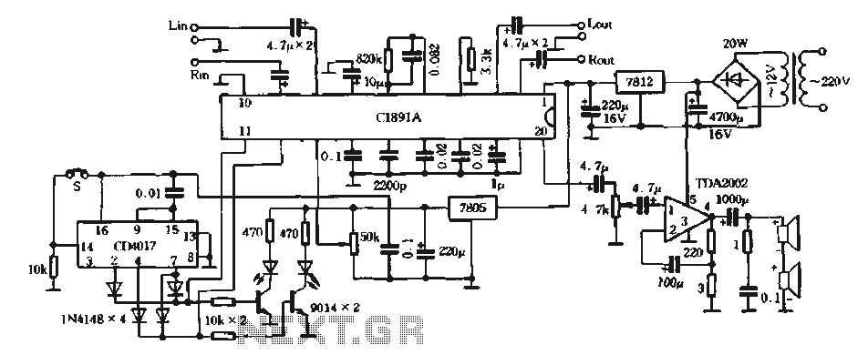
The surround processing section C1891A is a product from Sony Corporation of Japan that features a four-dimensional home theater surround processing circuit. It includes a parent roll phase-shifting circuit and a matrix surround sound amplifier. Additionally, it provides three...

This car audio amplifier circuit is based on the LA47536 audio amplifier integrated circuit designed by Sanyo. This audio amplifier circuit is specifically designed for car audio power amplifiers. The LA47536 car audio amplifier IC features four output channels...
This circuit is similar to the one above but uses positive feedback to get a little more amplitude to the speaker. I copied it from a small 5 transistor radio that uses a 25 ohm speaker. In the circuit...
Both transistors utilized in the circuit are low-noise types. Initially, the BC650C, an ultra-low noise device, was employed. However, due to its scarcity, the BC109C serves as a suitable replacement. The circuit exhibits a high tolerance for various devices...