
OP-AMP or comparator Astable multivibrator

The astable multivibrator is a fundamental circuit used for generating square waves and is characterized by its lack of a stable state, continuously switching between high and low outputs. In this schematic, the power supply voltage (Vcc) is set to 24V, which powers the entire circuit. The output voltage low (Vol) is defined as 1V, while the output voltage high (Voh) is set at 21V, indicating the swing of the output signal.
The time constant of the circuit is influenced by the resistor R1, valued at 1kΩ, and the capacitor C1, which has a capacitance of 100nF. The time constant (τ) can be calculated using the formula τ = R1 * C1, which determines the charging and discharging cycles of the capacitor, thereby affecting the frequency of oscillation.
The resistors R2, R3, and R4, all valued at 100kΩ, are used to set the reference voltages and feedback within the circuit. These resistors help establish the thresholds for the comparator (E1), which compares the voltage levels at its inputs and drives the output high or low based on the comparison. The voltage levels for the comparator's operation are defined in a lookup table, indicating specific input-output relationships.
Transient analysis is configured to run for 500μs, allowing observation of the waveform generated by the astable multivibrator over time. This analysis provides insight into the timing characteristics and stability of the generated square wave, essential for applications requiring precise timing signals. Overall, this simulation schematic serves as a comprehensive guide for constructing an astable multivibrator circuit, demonstrating key parameters and operational principles.Simulation schematic for astable multivibrator Parameters Vcc=24 Vol=1 Voh=21 Power supply Vcc Vcc 0 {Vcc} Time constant R1 Vo Vc 1K C1 Vc 0 100n. IC V(Vc)=0 * *Reference R2 Vo Vr 100K R3 Vcc Vr 100K R4 Vr 0 100K * *Comparator E1 Vo 0 Vr Vc table=(-1m {Vol} -1u {Vol} 1u {Voh} 1m {Voh}) *.
TRAN 500u. END 🔗 External reference
Related Circuits
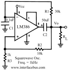
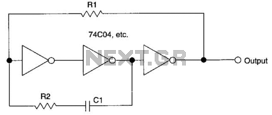
Several operational amplifier circuits are presented here, configured as square wave oscillators. A square wave is a periodic pulse train with a 50 percent duty cycle. The operational amplifier functions as a high-gain amplifier, and oscillation is achieved with...
Astable or free-running multivibrators have been used in home-built amateur radio equipment for many years. The basic circuit is a two-stage amplifier with AC-coupled feedback from output to input. One transistor stage is on (conducting current) while the other...
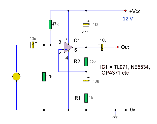
A high-quality microphone preamplifier utilizing a single power supply, suitable for both dynamic and electret microphones. The operational amplifier (op-amp) employed can be any low-noise, high-performance type, such as the NE5534, TL071, or OPA 371. The schematic illustrates the...
When this circuit is activated, the inherent offset of the devices acts as an automatic starting voltage. The output voltage V0 becomes positive, and the positive feedback through R2 and R1 drives the output to saturation. The elevated voltage...
This circuit employs a protective resistor R2 along with a feedback resistor R1. Together, these components create a voltage divider that lowers the input voltage amplitude for IC1-a, ensuring that the protective diodes remain inactive. This arrangement enhances the...
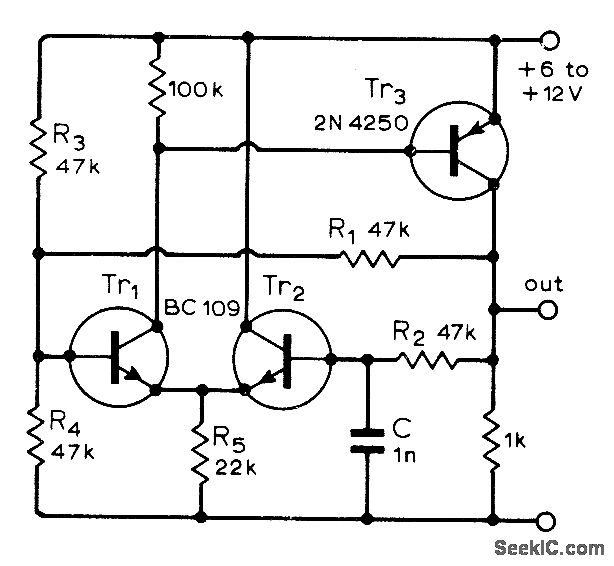
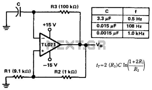
A single-capacitor circuit exhibits reliability across a wide range of temperatures, voltages, and transistor gains. The frequency varies by only 0.05% when the supply voltage changes between 6V and 12V. Timing adjustments can be made using resistors R1 and...