
Opamp Design and Test Board

The project described involves the use of a medium-sized un-etched printed circuit board (PCB) as a prototyping platform. This approach allows for flexibility in circuit design and experimentation, making it suitable for rapid development and testing of electronic concepts. The un-etched PCB serves as a versatile base where components can be placed and connected without the need for a pre-defined circuit layout.
To create the prototype, the following components may be utilized: resistors, capacitors, integrated circuits (ICs), transistors, and connectors, depending on the specific application being tested. The layout on the PCB can be customized according to the circuit requirements, allowing for modifications and adjustments as ideas evolve.
The un-etched PCB can be easily cut to size, accommodating various project scales. It is advisable to use a soldering iron for attaching components securely to the board, ensuring reliable electrical connections. Additionally, jumper wires can be employed for connecting different parts of the circuit, facilitating easy alterations during the prototyping phase.
For power supply, a standard voltage source may be utilized, ensuring it matches the requirements of the components used. The prototyping process may also involve the use of a breadboard for initial testing before finalizing the design on the PCB.
Overall, this prototyping method is cost-effective and provides a practical approach for developing and refining electronic ideas, making it an ideal choice for hobbyists and engineers alike.This project is basically what I use for a quick prototype, or for just mucking about with an idea. It is easy to make, and only needs a medium size sheet of un-etched printed circuit board (or possibly two). This can usually be obtained from electronics suppliers, and is not overly expensive. 🔗 External reference
Related Circuits
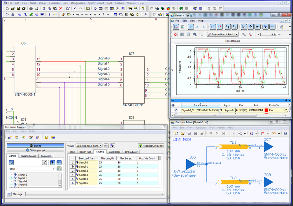
The CR-5000 EDA design suite provides the most advanced PCB design functionality currently available. It is constraints driven, from schematic capture through board layout, to the output of manufacturing data. More: This means that the rules you apply early...
This is a simple servo tester which will comprehensively test the capabilities of almost any modern servo. It has two pushbuttons, CENTRE and SWEEP and a potentiometer which works as follows: - CENTRE Does exactly that, centers the servo,...
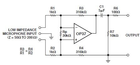
This microphone preamp schematic is an electronic circuit project utilizing the OP37 operational amplifier from Analog Devices. It functions as a fixed-gain transformerless microphone preamp, amplifying differential signals from low-impedance microphones by 50 dB, with an input impedance of...
Our CONTINUITY TESTER gives an audible indication of continuity between the probes so you can keep your eyes on the probe tip. Secondly its response-time is very short so that you can make lots of tests very quickly while...
Instructions for constructing a circuit on veroboard by interpreting the schematic. Experienced constructors can directly reference the schematic to begin assembly, utilizing their knowledge of component placement and efficient use of veroboard space. Beginners should have certain foundational skills,...
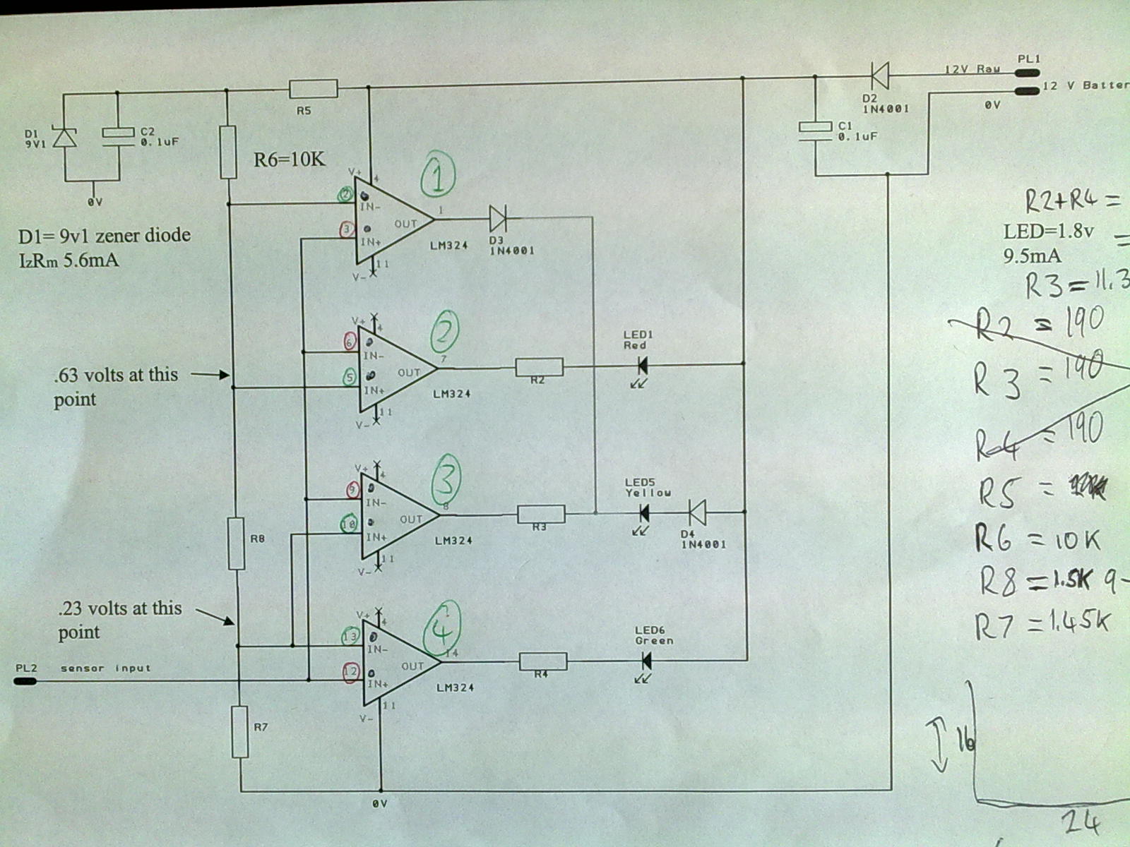
A 12V power supply is connected to the positive terminal, allowing current to flow through a protection diode and a capacitor that smooths the voltage. A zener resistor (R5) limits the current to the zener diode, which regulates the...